Brushless DC Power Tools

A technology of electric tools and transmission mechanism, which is applied in the field of brushless DC electric tools, which can solve the problems of reduced service life of the machine, easy blockage of the filter, and no products available, and achieves the advantages of prolonging the service life, good cooling effect, and fast heat dissipation Effect

Active Publication Date: 2018-06-05
ZHEJIANG BODA IND
View PDF9 Cites 3 Cited by
  • Summary
  • Abstract
  • Description
  • Claims
  • Application Information

AI Technical Summary

Problems solved by technology

Due to the harsh working environment of brushless DC electric tools, a large amount of dust will be generated during grinding, cutting, drilling, polishing, etc. During the working process, a large amount of dust and particles will enter the motor from the air inlet window, especially After iron powder or iron chips enter the motor, they will be absorbed by the permanent magnet rotor on the surface of the rotor. Over time, the iron powder and iron chips will fill the air gap between the stator and rotor, making it difficult for the permanent magnet rotor to rotate, resulting in permanent magnet The brushless motor is damaged and scrapped, which greatly reduces the service life of the machine
At present, although there are a small number of brushless DC power tools that add a filter to the air inlet to block granular dust, although it can achieve a certain effect, because the filter is fixed in the housing, it is inconvenient to disassemble, clean, and replace, resulting in a The net is easy to block, which affects the cooling effect of the motor
In response to the above problems, many manufacturers and people of insight have carried out research and development, but so far no ideal products have come out

Method used


Image

  • Brushless DC Power Tools
  • Brushless DC Power Tools
  • Brushless DC Power Tools

Examples


Embodiment Construction

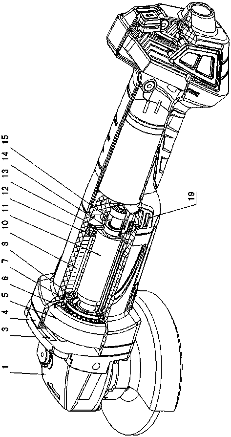
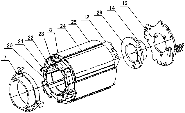
[0016] Figure 1 to Figure 4 As shown, the present invention creates a specific embodiment of a brushless DC power tool, which includes a head shell 1, a transmission mechanism 2, a middle cover 4, a windshield ring 5, a cooling fan 6, a casing 9, a stator 10, a permanent Magnetic rotor 11, handle 16, working head 18, handle 16 is provided with air inlet 19, head shell 1 is provided with air outlet 3, stator 10 is fixed on the casing 9, and permanent magnet rotor 11 in stator 10 is rotatably Set on the middle cover 4 and the casing 9, the cooling fan 6 is fixed on the rotating shaft of the permanent magnet rotor 11, the working head 18 is fixed on the output shaft of the transmission mechanism 2, the stator 10 includes a stator core 25, a stator coil 22. Front and rear skeletons 8, 12, bushings 28, several winding slots 27 are arranged on the stator core 25, bushings 28 are installed in the middle of the winding slots 27, front and rear skeletons 8, 12 are correspondingly inst...


PUM


Abstract

The invention discloses a brushless direct-current electric tool.A stator (10) comprises a stator core (25), stator coils (22), a front skeleton (8), a rear skeleton (12) and a lining (28), winding grooves (27) are formed in the stator core (25), the lining (28) is installed in the winding grooves (27), the front skeleton (8) and the rear skeleton (12) are correspondingly installed in the winding grooves (27) in the two ends of the stator core (25), the stator coils (22) are wound around the front skeleton (8) and the rear skeleton (12) on the winding grooves (27) and the lining (28), notches penetrating through the winding grooves (27) are correspondingly formed in the front skeleton (8), the rear skeleton (12) and the lining (28), an isolation notch wedge (21) is embedded into each notch, and the isolation notch wedges (21), and the front skeleton (8), the rear skeleton (12) and the lining (28) are matched between the adjacent stator coils (22) to form a stator inner ventilating channel (23), wherein an inlet and an outlet of the stator inner ventilating channel (23) are communicated with an air inlet (19) and an air outlet (3) respectively.By the adoption of the structure, the brushless direct-current electric tool has the advantages of being simple and reasonable in structure, convenient to produce and machine and safe and reliable in operation, the stator is good in ventilating and cooling effect, and a rotor is good in dustproof effect.

Description

technical field [0001] The invention relates to an electric tool, in particular to a brushless DC electric tool with good cooling and heat dissipation and dust-proof effects. Background technique [0002] There are many types of brushless DC power tools, including angle grinders, cutting machines, electric drills, impact drills, electric hammers, polishers, etc., which are hand tools driven by brushless DC motors. When the brushless DC power tool is working, because the motor will heat up, it needs to be dissipated by a cooling fan. Therefore, the handle at the rear of the brushless DC power tool housing is provided with an air inlet for sucking in external air to reduce the temperature of the motor. And the air exhaust port that is arranged on the head shell of the front part of the shell to discharge the heated air. Due to the harsh working environment of brushless DC electric tools, a large amount of dust will be generated during grinding, cutting, drilling, polishing, e...

Claims


Application Information

Patent Timeline
Patent Type & Authority Patents(China)
IPC IPC(8): H02K9/06H02K3/24H02K1/20H02K5/10
CPCH02K1/20H02K3/24H02K5/10H02K9/06
Inventor 胡丽姬吴浩东胡新昌
Owner ZHEJIANG BODA IND
Why Eureka
Try Eureka