A remote monitoring system and method for mountain disasters in scenic spots
A remote monitoring and mountain technology, applied to instruments, alarms, etc., can solve problems such as difficult wiring, complex structure, and low monitoring accuracy, and achieve the effects of cost control, accurate measurement, and reduced usage
- Summary
- Abstract
- Description
- Claims
- Application Information
AI Technical Summary
Problems solved by technology
Method used
Image
Examples
Embodiment 1
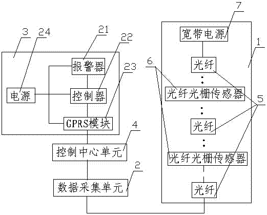
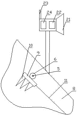
[0040] Such as Figure 1 to Figure 3 As shown: this embodiment provides a remote monitoring system for mountain disasters in scenic spots, including a vibration monitoring unit 1, a data acquisition unit 2, an on-site alarm unit 3 and a control center unit 4, and the vibration monitoring unit 1 includes several optical fiber 5 A fiber grating sensor 6 connected in sequence, one end of the vibration monitoring unit 1 is provided with a broadband light source 7, the other end of the vibration monitoring unit 1 is connected to the data acquisition unit 2 through the optical fiber 5, and the data acquisition unit 2 , the control center unit 4 and the on-site alarm unit 3 are connected in sequence, and the vibration monitoring unit 1 is wound and arranged on the mountain body 8 .
[0041] The present invention is especially aimed at the mountain in the scenic spot where the mixed material of earth and rock is, and such mountain is prone to falling rocks and landslides, which will c...
Embodiment 2
[0047] Such as figure 1 , figure 2 and Figure 4 As shown: the present embodiment also provides a remote monitoring system for mountain disasters in scenic spots, including a vibration monitoring unit 1, a data acquisition unit 2, an on-site alarm unit 3 and a control center unit 4, and the vibration monitoring unit 1 includes several 5 sequentially connected fiber grating sensors 6, one end of the vibration monitoring unit 1 is provided with a broadband light source 7, the other end of the vibration monitoring unit 1 is connected to the data acquisition unit 2 through the optical fiber 5, and the data acquisition unit 2. The control center unit 4 and the on-site alarm unit 3 are sequentially connected, and the vibration monitoring unit 1 is wound and arranged on the mountain body 8 .
[0048] A line stretcher 12 is arranged on the optical fiber 5, and the line stretcher 12 includes a box body 13. An inlet 14 and an outlet 15 are arranged at both ends of the box body 13, an...
Embodiment 3
[0051] Such as figure 1 and image 3 As shown: the present embodiment also provides a remote monitoring system for mountain disasters in scenic spots, including a vibration monitoring unit 1, a data acquisition unit 2, an on-site alarm unit 3 and a control center unit 4, and the vibration monitoring unit 1 includes several 5 sequentially connected fiber grating sensors 6, one end of the vibration monitoring unit 1 is provided with a broadband light source 7, the other end of the vibration monitoring unit 1 is connected to the data acquisition unit 2 through the optical fiber 5, and the data acquisition unit 2. The control center unit 4 and the on-site alarm unit 3 are sequentially connected, and the vibration monitoring unit 1 is wound and arranged on the mountain body 8 .
[0052] The data acquisition unit 2 includes a fiber grating network analyzer, and the control center unit 4 includes an industrial control computer. The fiber grating network analyzer detects the change ...
PUM
 Abstract
Description
Claims
Application Information
 - Generate Ideas
- Intellectual Property
- Life Sciences
- Materials
- Tech Scout
- Unparalleled Data Quality
- Higher Quality Content
- 60% Fewer Hallucinations
Browse by: Latest US Patents, China's latest patents, Technical Efficacy Thesaurus, Application Domain, Technology Topic, Popular Technical Reports.
© 2025 PatSnap. All rights reserved.Legal|Privacy policy|Modern Slavery Act Transparency Statement|Sitemap|About US| Contact US: help@patsnap.com


