
Wearing state detection method and device of wearable equipment

A wearable device, wearing state technology, applied in measurement devices, timers of integrated devices, measurement of acceleration, etc., can solve problems such as waste of power consumption, and achieve the effect of low power consumption and saving power consumption

Active Publication Date: 2016-07-13
GOERTEK INC
View PDF12 Cites 83 Cited by
  • Summary
  • Abstract
  • Description
  • Claims
  • Application Information

AI Technical Summary

Problems solved by technology

[0004] In view of the above analysis, the present invention provides a wearable state detection method and device to solve the problem of power consumption waste caused by opening useless applications when the wearable device is in the non-wearing state

Method used


Image

  • Wearing state detection method and device of wearable equipment
  • Wearing state detection method and device of wearable equipment
  • Wearing state detection method and device of wearable equipment

Examples


Embodiment 1

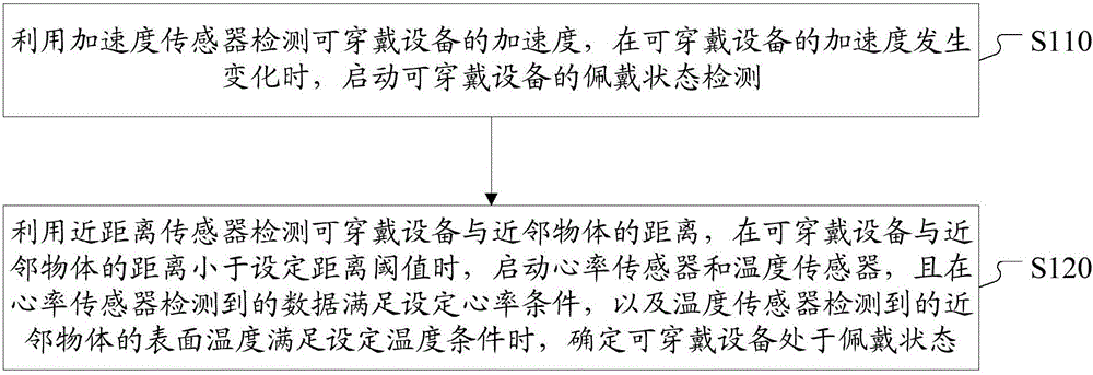
[0027] figure 1 The flow chart of the wearing state detection method of the wearable device provided in this embodiment, the wearable device is provided with an acceleration sensor, a proximity sensor, a heart rate sensor and a temperature sensor, such as figure 1 As shown, the method includes:

[0028] S110, use the acceleration sensor to detect the acceleration of the wearable device, and start the detection of the wearing state of the wearable device when the acceleration of the wearable device changes.

[0029] S120, using the proximity sensor to detect the distance between the wearable device and the nearby object, and when the distance between the wearable device and the nearby object is less than the set distance threshold, start the heart rate sensor and the temperature sensor, and the data detected by the heart rate sensor meets the set When the heart rate condition and the surface temperature of the nearby object detected by the temperature sensor meet the set tempe...

Embodiment 2

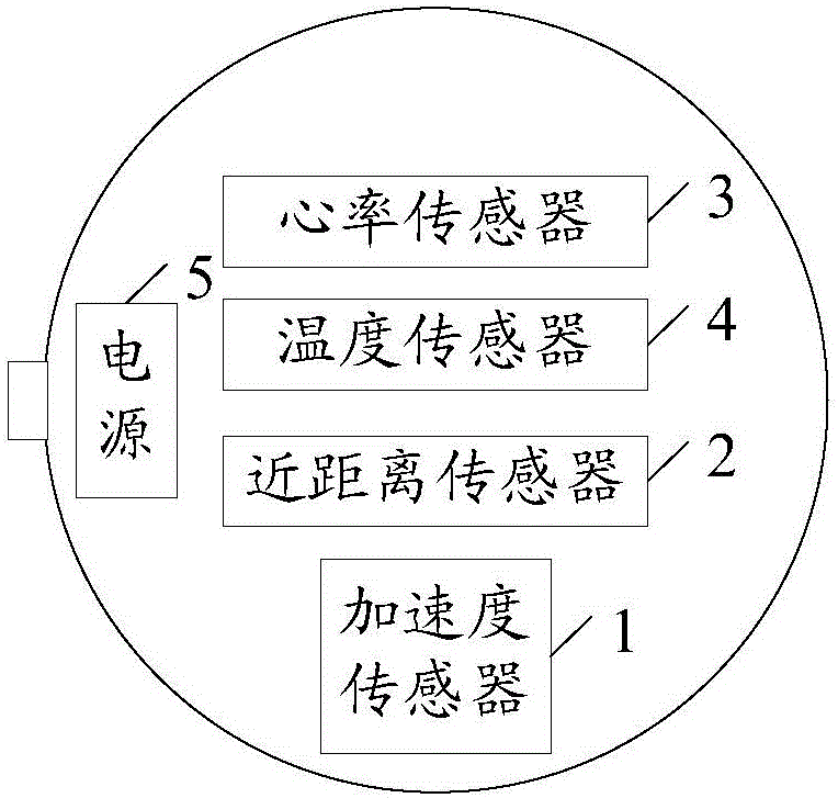
[0075] Based on the same technical concept as that of Embodiment 1, this embodiment provides a device for detecting a wearing state of a wearable device, and the wearable device is provided with an acceleration sensor, a proximity sensor, a heart rate sensor, and a temperature sensor.

[0076] Figure 6 A schematic structural diagram of a wearing state detection device for a wearable device provided in Embodiment 2, such as Figure 6 as shown, Figure 6 The wearing state detection device in includes:

[0077] The starting unit 61 is used to detect the acceleration of the wearable device by using the acceleration sensor, and start the proximity sensor to detect the wearing state of the wearable device when the acceleration of the wearable device changes;

[0078] The detection unit 62 is configured to use the proximity sensor to detect the distance between the wearable device and the nearby object, and when the distance between the wearable device and the nearby object is les...


PUM


Abstract

The invention discloses a wearing state detection method and device of wearable equipment. The method comprises that an accelerometer is used to detect the acceleration of the wearable equipment, and when the acceleration of the wearable equipment changes, wearing state detection for the wearable equipment is started; a near-distance sensor detects the distance between the wearable equipment and an neighbor object, a heart rate sensor and a temperature sensor are started when the distance is lower than a set distance threshold, and wearable equipment is determined to be in the wearing state when data detected by the heart rate sensor satisfies the set heart rate condition and the surface temperature, detected by the temperature sensor, of the neighbor object satisfies the set temperature condition. According to the invention, the accelerometer is used to start wearing state detection for the wearable equipment, power consumption of the wearable equipment can be effectively reduced, and during wearing state detection, different types of sensor are used comprehensively to detect the wearing state of the wearable equipment accurately.

Description

technical field [0001] The present invention relates to the technical field of state recognition, in particular to a method and device for detecting the wearing state of a wearable device. Background technique [0002] With the continuous advancement of mobile technology, smart watches, as a hot spot in the smart terminal industry, have increasingly broad application fields. However, limited by the size of the smart watch, the battery capacity cannot be too large, and the battery life is limited. Therefore, effectively saving electricity consumption will become an important research direction. [0003] Due to some functions in the smart watch, such as: step counting function, health data recording function, only when the user wears the smart watch, can the effective or meaningful data feedback be obtained; when the user is not wearing the smart watch, the smart watch The above functions that are turned on will cause a waste of power consumption, thereby reducing the use ti...

Claims


Application Information

Patent Timeline
IPC IPC(8): G01D21/02A61B5/00A61B5/01A61B5/0205A61B5/0245
CPCA61B5/01A61B5/02055A61B5/0245A61B5/681A61B5/6824A61B5/6844G01D21/02A61B5/0205G04C3/002A61B2560/029A61B5/02438A61B2560/0209A61B2562/0219A61B2562/0257G04G21/025G06F1/163G06F1/3231G06F1/3287Y02D10/00G06F1/3206G01P15/0802
Inventor 李海波
Owner GOERTEK INC
Learn More