Hinge
A hinge and articulation technology, which is applied to hinges with pins, door/window fittings, hinges, etc., can solve the problems of unstable structure, low safety performance, and high cost, and achieve simple and stable structure, low cost, and high safety performance. Good results
- Summary
- Abstract
- Description
- Claims
- Application Information
AI Technical Summary
Problems solved by technology
Method used
Image
Examples
Embodiment 1
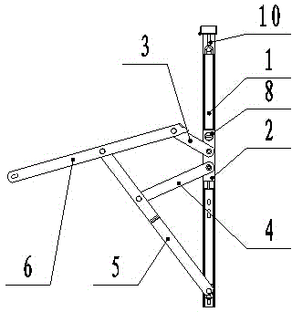
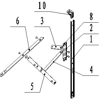
[0024] Embodiment one: combined with attached figure 1 , 2And 5, a kind of hinge, comprises slide rail 1, slide block 2, cam 8 and link mechanism, slide block 2 is connected with slide rail 1 slidingly, and link mechanism is composed of cantilever I3, cantilever II4, support arm I5 and swing arm 6 One end of the cantilever I3 and the cantilever II4 are both hinged with the slider 2, the other end of the cantilever I3 is hinged with one end of the swing arm 6, the other end of the cantilever II4 is hinged with the support arm I5, and one end of the support arm I5 is hinged with the slide rail 1 , the other end is hinged with the middle part of the swing arm 6, the sum of the length of the support arm I5 and the length between the two hinge points of the swing arm 6 is less than the length from the hinge point of the support arm I5 and the slide rail 1 to the other end of the slide rail 1, The maximum included angle formed by the centerline of the swing arm 6 and the centerline...
Embodiment 2
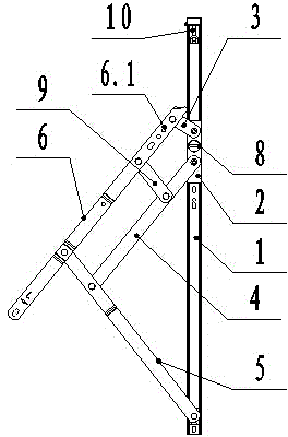
[0025] Embodiment two: combined with attached image 3 , 4 And 5, a kind of hinge, comprise slide rail 1, slide block 2, auxiliary link 7, cam 8, support arm II9, positioning block 10 and link mechanism, slide block 2 is slidingly connected with slide rail 1, and link mechanism consists of The cantilever I3, the cantilever II4, the support arm I5 and the swing arm 6 are composed, one end of the cantilever I3 and the cantilever II4 are hinged with the slider 2, and one end of the swing arm 6 is provided with a row of adjustment holes 6.1 which are matched with the auxiliary link 7, The auxiliary link 7 is hinged with the end of the cantilever I3, the other end of the cantilever II4 is hinged with the support arm I5, one end of the support arm I5 is hinged with the slide rail 1, the other end is hinged with the middle of the swing arm 6, and one end of the support arm II9 is hinged with the The cantilever II4 is hinged, the other end of the support arm II9 is hinged with th...
Embodiment 3
[0026] Embodiment three: combined with attached figure 1 with 2 , a rigid force application method using a hinge structure, the application method is: when the door and window are closed, the linkage mechanism gradually moves closer to the slide rail 1, the slider 2 gradually slides horizontally along the slide rail 1, and the cantilever I3 and the cantilever II4 first contact with the The slide rail 1 overlaps, the hinge point of the cantilever I3 and the swing arm 6, the hinge point of the swing arm 6 and the support arm I5, and the hinge point of the support arm I5 and the slide rail 1 form three vertices of a triangle, the cantilever II4, the support arm I5, The hinge point between the slide block 2 and the slide rail 1 also forms three vertices of a triangle, between the swing arm 6 and the support arm I5, between the cantilever II4 and the support arm I5, there is a rigidly connected tension force, so that the doors and windows cannot Easy to close, when the slider 2 sl...
PUM
 Abstract
Description
Claims
Application Information
 - R&D
- Intellectual Property
- Life Sciences
- Materials
- Tech Scout
- Unparalleled Data Quality
- Higher Quality Content
- 60% Fewer Hallucinations
Browse by: Latest US Patents, China's latest patents, Technical Efficacy Thesaurus, Application Domain, Technology Topic, Popular Technical Reports.
© 2025 PatSnap. All rights reserved.Legal|Privacy policy|Modern Slavery Act Transparency Statement|Sitemap|About US| Contact US: help@patsnap.com


