a roof device

A floor and web technology, applied to floors, buildings, building components, etc., can solve the problems of short service life of fireproof boards, lack of large-scale promotion and use, and increase the load bearing of buildings, so as to achieve high impact resistance and facilitate standardization The effect of high construction and support strength

Active Publication Date: 2018-09-14
张波
View PDF7 Cites 0 Cited by
  • Summary
  • Abstract
  • Description
  • Claims
  • Application Information

AI Technical Summary

Problems solved by technology

The disadvantage of this kind of floor structure is: the construction is complicated, and the water, electricity, and heating pipes are covered by concrete, which makes maintenance extremely difficult. At the same time, it also increases the load-bearing capacity of the building.
At present, although water, electricity, and heating pipes are installed below the structural layer to solve the problem of difficult maintenance, the installation of water, electricity, and heating pipes under the structural layer requires hanging items and fireproof boards, and the service life of the fireproof boards is longer. short and needs to be replaced frequently, which brings great inconvenience and potential safety hazards to residents. Therefore, this structure has not been widely used

Method used


Image

  • a roof device
  • a roof device
  • a roof device

Examples


Embodiment Construction

[0007] The present invention will be further described with reference to the accompanying drawings.

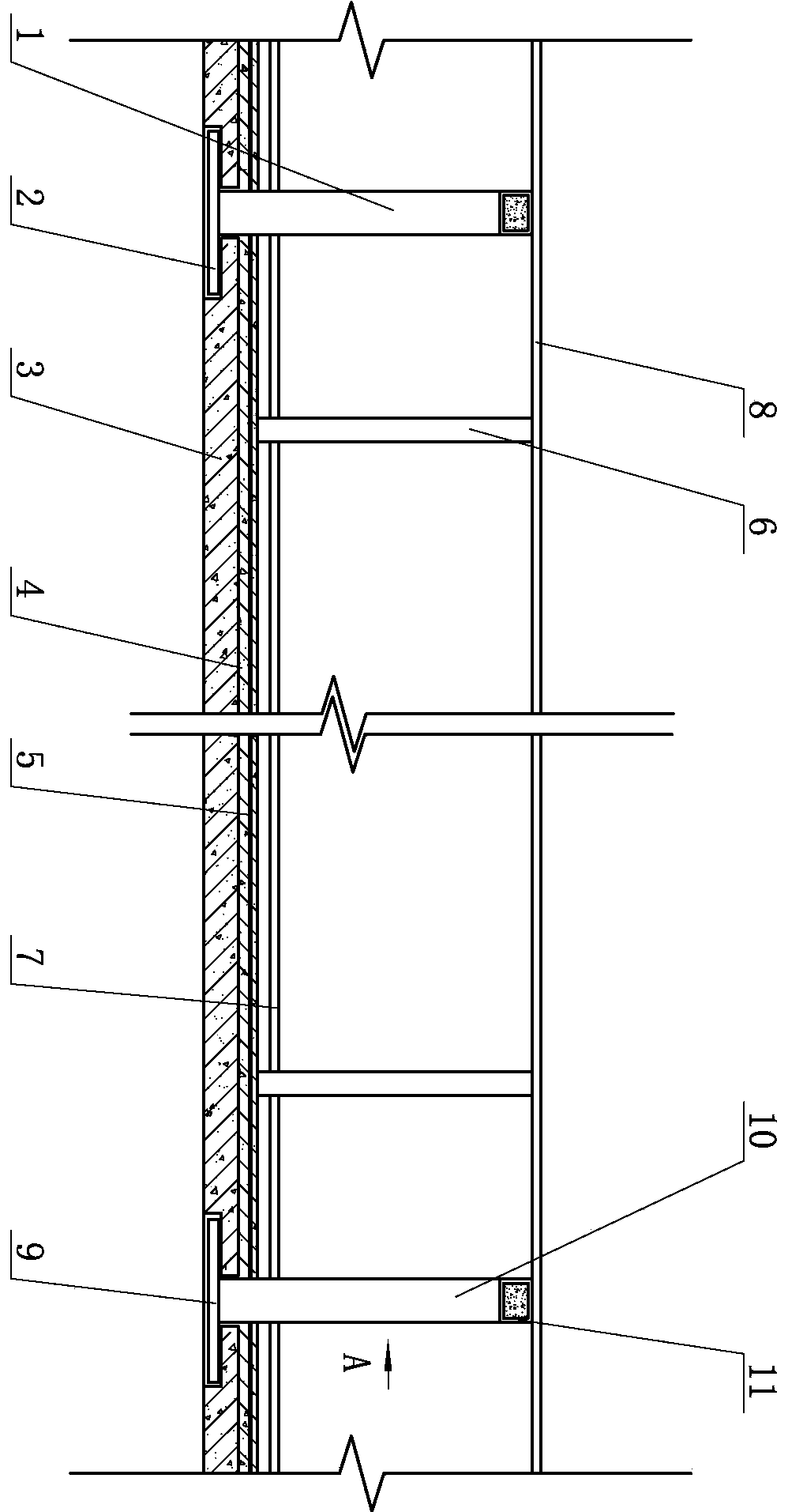
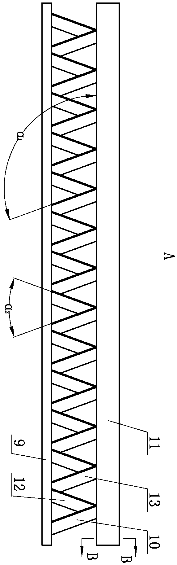
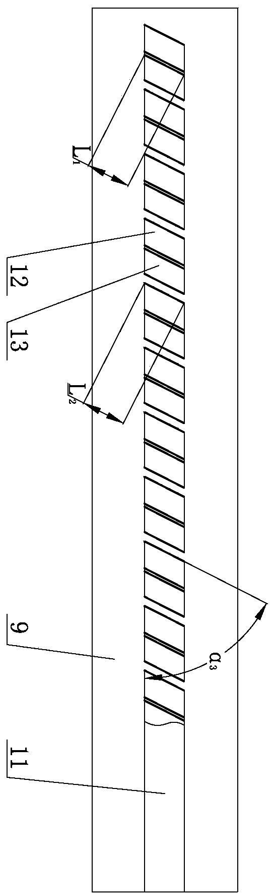
[0008] 3 in the figure is a prefabricated floor, the upper part of the prefabricated floor 3 is provided with a floor 8, and a cavity 14 is provided between the prefabricated floor 3 and the floor 8, and several first webs 10 and several second webs 12 are installed in the cavity 14. The upper ends of the first web 10 and the second web 12 are connected to the wing bar 11, and the wing bar 11 is connected to the floor 8, and the lower ends of the first web 10 and the second web 12 are connected to the support plate 9, and the support plate 9 Connected with the prefabricated bottom plate 3, the first angle α is set between the first web 10 and the wing bar 11 1 , the first included angle α 1 Greater than 90°, a second angle α is set between the first web 10 and the second web 12 2 , the second included angle α 2 It is an acute angle, several first webs 10 are parallel and ev...


PUM


Abstract

A floor system device comprises a prefabricated bottom plate.A floor is arranged on the upper portion of the prefabricated bottom plate.A cavity is arranged between the prefabricated bottom plate and the floor.A plurality of first web plates and a plurality of second web plates are mounted in the cavity.The upper ends of the first web plates and the upper ends of the second web plates are all connected with a wing rod.The wing rod is connected with the floor.The lower ends of the first web plates and the lower ends of the second web plate are all connected with a supporting plate.The floor system device has the advantages of being extremely high in impact resistance, good in fireproof performance, high in stability, good in anti-seismic property and high in construction speed, facilitating standard construction and the like.

Description

technical field [0001] The invention relates to construction engineering, and is a floor covering device. Background technique [0002] Existing floor structures are cast-in-place or cast-in-place after laying prefabricated slabs. Water and electricity pipelines are generally laid between the surface layer and the structural layer, and some projects are arranged at the bottom of the floor. The disadvantage of this floor structure is that the construction is complicated, and the water, electricity, and heating pipes are covered by concrete, which makes maintenance extremely difficult, and simultaneously increases the load bearing of the building. At present, although water, electricity, and heating pipes are installed below the structural layer to solve the problem of difficult maintenance, the installation of water, electricity, and heating pipes under the structural layer requires hanging items and fireproof boards, and the service life of the fireproof boards is longer. I...

Claims


Application Information

Patent Timeline
Patent Type & Authority Patents(China)
IPC IPC(8): E04C2/52E04B5/48
CPCE04B5/48E04C2/50E04C2/521
Inventor 张波张树辉
Owner 张波
Why Eureka
Try Eureka