
Slow descent method for high-altitude escape and high-altitude escape device

An escape device and slow-down technology, applied in life-saving equipment, building rescue, etc., can solve the problems of high site structure requirements, complex installation, complex structure, etc., and achieve low site requirements, convenient continuous use, and hook structure simple effect

Inactive Publication Date: 2016-07-13
GUANGDONG COMM POLYTECHNIC
View PDF9 Cites 1 Cited by
  • Summary
  • Abstract
  • Description
  • Claims
  • Application Information

AI Technical Summary

Problems solved by technology

[0002] At present, there are more and more high-rise and super-high-rise buildings in cities. Once disasters such as fires and earthquakes occur, and people are trapped in the house by the fire and cannot escape, they can only wait for firefighters to come to the rescue. People's life safety has been greatly threatened. For the above problems, people have developed many escape methods and escape tools. There are many high-altitude escape devices in the prior art, but there are the following problems: 1. Complex structure, heavy volume, high manufacturing cost, Difficult to be popularized and applied; 2. Difficult to operate, and it is difficult for trapped persons to operate in emergency situations such as disasters; 3. Does not have automatic return function, even if it has return function, it needs to be operated by trapped persons at high places to return High, unable to adapt to the use when many people need to escape; 4. The installation is complicated, and the structural requirements for the use site are relatively high

Method used


Image

  • Slow descent method for high-altitude escape and high-altitude escape device
  • Slow descent method for high-altitude escape and high-altitude escape device
  • Slow descent method for high-altitude escape and high-altitude escape device

Examples


Embodiment Construction

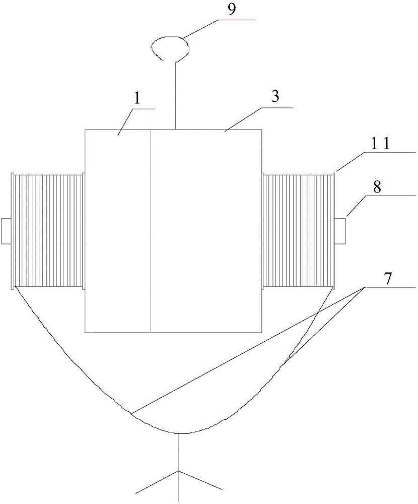
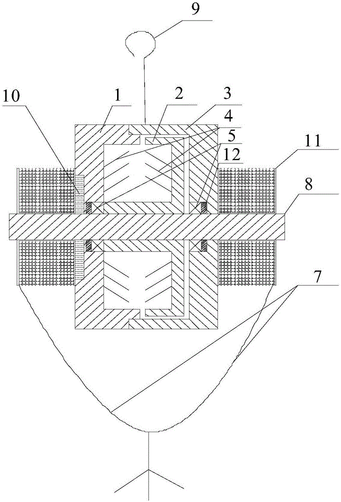
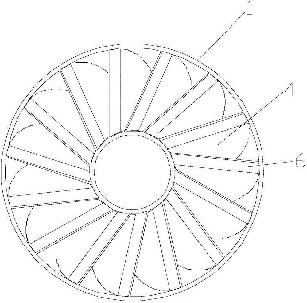
[0024] like Figure 1-4 As shown, a high-altitude escape device is mainly composed of a descending device, a lifeline 7 and a hook 9. The descending device includes a stator impeller 1, a rotor impeller 2, a housing 3, a bearing 5, and a shaft 8. The stator impeller 1 and The rotor impellers 2 each include a disc structure, the two disc structures are placed opposite to each other and can rotate relative to each other, the front inclined blades 4 around the disc axis are installed on the opposite surfaces of the two disc structures, and the blade bone surface 6 is inclined The direction is the same as the relative rotation of the rotor impeller 2 and the stator impeller 1. The angle between the blade bone surface 6 and the shaft 8 ranges from 20 degrees to 50 degrees. The inner flange and outer flange set on the disc structure are connected, the outer flange of the stator impeller 1 and the casing 3 are fixedly sealed and connected to form a closed space, the closed space is f...


PUM


Abstract

The invention discloses a slow descent method for high-altitude escape and a high-altitude escape device using the slow descent method. The method utilizes a reverse damping torque generated when a rotor impeller and a stator impeller rotate at a high speed relatively in oil liquid to suppress the rotating speed of the rotor impeller, the device mainly comprises a descent control device, a life-saving rope and a fixing device, wherein the descent control device comprises the stator impeller, the rotor impeller, a shell and a shaft, the stator impeller and the rotor impeller are of two disc structures which are oppositely placed and capable of rotating relative to each other and having front inclined blades on two opposite surfaces respectively, the stator impeller and the shell are fixedly and hermetically connected to form a sealed space filled with oil, the rotor impeller is placed in the sealed space and can rotate relative to the stator impeller and the shell through the shaft, one end of the life-saving rope is connected to the shaft, and the other end thereof is connected with a user or life-saving equipment. The slow descent method disclosed by the invention is safe and reliable, and the high-altitude escape device disclosed by the invention is simple in structure, safe and firm, convenient to operate and wide in application range.

Description

technical field [0001] The invention relates to the field of high-altitude emergency escape, in particular to a slow-down method for high-altitude escape and a high-altitude escape device using the method. Background technique [0002] At present, there are more and more high-rise and super-high-rise buildings in cities. Once disasters such as fires and earthquakes occur, and people are trapped in the house by the fire and cannot escape, they can only wait for firefighters to come to the rescue. People's life safety has been greatly threatened. For the above problems, people have developed many escape methods and escape tools. There are many high-altitude escape devices in the prior art, but there are the following problems: 1. Complex structure, heavy volume, high manufacturing cost, Difficult to be popularized and applied; 2. Difficult to operate, and it is difficult for trapped persons to operate in emergency situations such as disasters; 3. Does not have automatic return...

Claims


Application Information

Patent Timeline
Patent Type & Authority Applications(China)
IPC IPC(8): A62B1/14A62B1/18
CPCA62B1/14A62B1/18
Inventor 黄俊刚张胜宾黄志永李军孟国强
Owner GUANGDONG COMM POLYTECHNIC
Learn More