
Wire clip for photovoltaic tracking device and cable collection anchoring device with wire clip

An anchoring device and tracker technology, which is applied in the direction of photovoltaic power generation, photovoltaic modules, electrical components, etc., can solve the problems of unsuitable cable anchoring, slow installation speed, and difficult wiring, etc. simple effect

Inactive Publication Date: 2016-07-06
SUZHOU JINSHAN SOLAR TECH
View PDF6 Cites 3 Cited by
  • Summary
  • Abstract
  • Description
  • Claims
  • Application Information

AI Technical Summary

Problems solved by technology

[0004] In order to solve the technical problems that the traditional binding and anchoring methods of common and fixed brackets have slow installation speed, difficult wiring, and are not suitable for cable anchoring of tracking brackets, the present invention provides a cable clamp for photovoltaic trackers and a cable with the clamp Pooling Anchors

Method used


Image

  • Wire clip for photovoltaic tracking device and cable collection anchoring device with wire clip
  • Wire clip for photovoltaic tracking device and cable collection anchoring device with wire clip
  • Wire clip for photovoltaic tracking device and cable collection anchoring device with wire clip

Examples


Embodiment 1

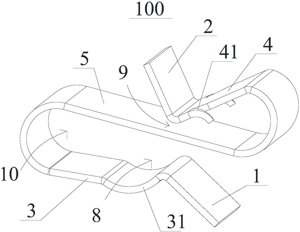
[0032] Please also refer to figure 1 and figure 2 , the typical solar tracker solar module boards 101 are arranged from south to north, and these solar module boards 101 need to be cabled in series, and the cables are collected to the cable collection line, such as the south side of the tracker row, the north side, or the middle of the row. In this example, if figure 1 shown on the left.

[0033] The cable anchoring device provided by the present invention is also called a cable sink anchoring device, which includes several parallel clamps 100 for photovoltaic power plants and auxiliary anchors used in conjunction with the clamps 100 . The cable harness anchoring device and several anchoring bases for anchoring numerous solar module panels constitute the main frame of a solar module panel anchoring device.

[0034] The present invention provides an anchoring device for cables. Auxiliary anchors, such as parallel clamps, use one side of the anchoring support of the anchor c...

Embodiment 2

[0041] Please also refer to Figure 8 and Figure 9 , the cable collection and anchoring device 200 of embodiment 2 is basically the same as that of embodiment 1, the difference is that the cable collection and anchoring device 200 of embodiment 2 is integrally formed in one structure (for example, the cable collection and anchoring device 200 can be bent by a flat plate into), so that the structural strength is greatly improved.

Embodiment 3

[0043] Please also refer to Figure 10 , 11 , 12. The cable collection and anchoring device 300 of Embodiment 3 is basically the same as the cable collection and anchoring device 100 of Embodiment 1, the difference is that in the cable collection and anchoring device 300 of Embodiment 3, the limiting member 3 and the limiting member Two 4 are respectively fixed on the adjacent two sides of the connector 5 .

[0044] The cable collection and anchoring device of Embodiments 1 and 2, that is, when the first limiting member 3 and the second limiting member 4 are respectively fixed on opposite sides of the connecting member 5, the cable 6 can be anchored on one side, and the outer substrate 7 can be anchored on the other side Or the photovoltaic device of the tracker is anchored on the bracket 7a, and the sink lines are collected to the cable collection end of the tracker in turn. Embodiments 1 and 2 have the following beneficial effects: 1. Less material, stable anchoring; 2. Ea...


PUM


Abstract

The invention discloses a wire clip for a photovoltaic tracking device and a cable collection anchoring device with the wire clip. The wire clip comprises a first limitation element, a second limitation element and a connection element, wherein the first limitation element and the second limitation element are respectively fixed on the two sides of the connection element, at least one arc groove is formed in the first limitation element, a first cable anchoring cavity is formed between the arc groove and the connection element and can be used for a cable to pass through, a foundation anchoring cavity is formed between the second limitation element and the connection element and can be used for clamping a substrate, and at least one inverted thorn is arranged on the second limitation element, extends towards the connection element and can prop against the substrate. The wire clip and a solar panel anchoring support or the frame of a photovoltaic solar panel can form a wire collection scheme; and compared with a traditional wire collection mode, the wire collection scheme has the advantages that anchoring is tight, materials are saved, and the installation speed is fast. The invention also discloses the cable collection anchoring device with the wire clip.

Description

technical field [0001] The invention relates to a wire clip and an anchoring device with the wire clip, in particular to a wire clip for a photovoltaic tracker and a cable collection and anchoring device with the wire clip. Background technique [0002] Renewable energy such as solar energy has become a key option to solve energy problems and achieve sustainable development. The main challenge in developing solar energy at present is the high cost. The solar automatic tracker can help solar photovoltaic or photothermal devices (such as photovoltaic panels, etc.) to receive sunlight at a better incident angle to improve power generation efficiency and reduce power generation costs. [0003] The cables of the photovoltaic power generation equipment on the tracker need to be collected to the combiner box or the inverter. The collection and anchoring devices and installation methods of the cables must be firm and will not loosen under the action of strong wind and self-weight. ...

Claims


Application Information

Patent Timeline
IPC IPC(8): H02G3/02H02S40/34
CPCH02G3/02H02S40/34Y02E10/50
Inventor 周印韩冲
Owner SUZHOU JINSHAN SOLAR TECH
Learn More