A siphon power generation system

A power generation system, siphon technology, applied in siphon pipes, hydropower, non-volume pumps, etc., can solve the problems of large project investment, long construction period, and high requirements for natural conditions, and achieve cost savings and reduce natural conditions. , The effect of shortening the construction period

Active Publication Date: 2018-09-07
北京易捷胜科技有限公司
View PDF8 Cites 0 Cited by
  • Summary
  • Abstract
  • Description
  • Claims
  • Application Information

AI Technical Summary

Problems solved by technology

[0005] The purpose of the present invention is to provide a hydroelectric power generation system that does not need to build interception water storage buildings and is applicable to low-speed and low-flow, so as to solve the problems that existing hydropower generation systems have high requirements on natural conditions, large project investment and long construction period

Method used


Image

  • A siphon power generation system
  • A siphon power generation system
  • A siphon power generation system

Examples


Embodiment 1

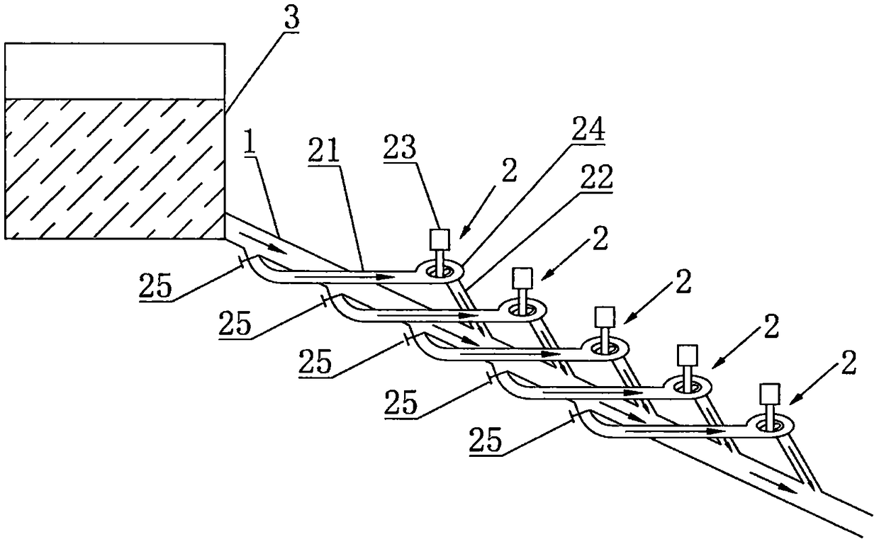
[0029] like figure 1 As shown, the siphon power generation system provided by Embodiment 1 of the present invention includes a main pipe 1 and a siphon power generation device 2, and the siphon power generation device 2 includes a branch pipe 21, a siphon pipe 22, a water turbine 24 and a generator 23, wherein the branch pipe 21 The water inlet of the siphon pipe 22 is connected with the main pipe 1, and the water outlet is connected with the water turbine 24; Downstream of the joint of the pipe 1, a water turbine 24 is connected with a generator 23 for driving the generator to generate electricity.

[0030] During use, according to the siphon principle, a vacuum is formed in the siphon tube 22 (the so-called vacuum here is relative to the atmospheric pressure, as long as it is lower than the atmospheric pressure, it can form a suction force on the water flow), and the pressure difference is used to make the water flow into the water turbine 24, like figure 1 As shown by the...

Embodiment 2

[0042] like figure 2 As shown, the second embodiment is basically the same as the first embodiment, and the similarities will not be repeated. The difference is that a plurality of main flow pipes 1 are arranged in the siphon power generation system, and the upper end of each main flow pipe 1 is connected to a water source. And distributed at different water levels of the water source, each main pipe 1 is provided with a plurality of siphon power generation devices 2 in the above-mentioned embodiments at intervals, and when the water source is sufficient, the water energy can be fully utilized to increase the power generation. The generators 23 in the power generating device 2 are all connected in series, and the generated electric power is incorporated into the grid.

[0043] Furthermore, in the case of insufficient water source, in order to ensure that at least some generators can work normally and stably, such as figure 2 As shown, a water level monitor 4 is set in the w...

Embodiment 3

[0045] like image 3 and Figure 4 As shown, the third embodiment is basically the same as the second embodiment, and the similarities will not be repeated. The difference is that the upper ends of the plurality of mainstream pipes are located at the same water level of the water source, that is, they are all distributed at the same water level in the water source. And through the water level monitor 4 and the second water control valve to control the water flow of the corresponding main pipe 1, to ensure that the siphon power generation device 2 provided on the other main pipe 1 can obtain sufficient water flow and perform normal power generation work.


PUM


Abstract

The invention relates to the technical field of power generation, in particular to a siphonic power generation system. The system comprises a main flowing pipe and a siphonic power generation device; the siphonic power generation device includes a branch flowing pipe, a siphon pipe, a water turbine and a generator; a water inlet of the branch flowing pipe is communicated with the main flowing pipe, and a water outlet is communicated with the water turbine; a water inlet of the siphon pipe is communicated with the water turbine, and a water outlet is communicated with the main flowing pipe; the connecting place between the water outlet of the siphon pipe and the main flowing pipe is positioned at the downstream of the connecting place between the water inlet of the branch flowing pipe and the main flowing pipe; and the water turbine is connected with the generator for driving the generator to generate electricity. The siphonic power generation system uses siphon and jet drainage, is suitable for water sources with higher water level fall, can be directly applied to such water sources as rivers with lower water level fall and slow water flowing speed, can continuously generate electricity without needing to build a closure water storage building, reduces the requirements of hydraulic power generation on natural conditions, shortens the power plant construction period, and saves the cost.

Description

technical field [0001] The invention relates to the technical field of power generation, in particular to a siphon power generation system. Background technique [0002] As a renewable clean energy, hydropower is still the main way of power supply at present. It has high power generation efficiency, low power generation cost, quick start-up and easy adjustment of the unit, but it is greatly affected by natural conditions. It is necessary to choose a place with a large water level drop, and to manually build hydraulic structures that can concentrate the water drop and regulate the flow, such as dams, diversion pipes, etc., so the project investment is large and the construction period is long. [0003] Therefore, to address the above shortcomings, it is necessary to provide a hydroelectric power generation system that does not require construction of interception water storage buildings and is applicable to low-speed and low-flow rates. Contents of the invention [0004] (...

Claims


Application Information

Patent Timeline
Patent Type & Authority Patents(China)
IPC IPC(8): F03B13/08F03B15/04F04F5/10F04F10/00
CPCF03B13/086F03B15/04F04F5/10F04F10/00F05B2220/706Y02E10/20
Inventor 李岩尹俊杰齐佳
Owner 北京易捷胜科技有限公司
Why Eureka
Try Eureka