Electromagnetic piling device and piling method
A piling device and electromagnetic technology, applied in sheet pile wall, construction, infrastructure engineering and other directions, can solve the problems of high noise self-weight and soil layer requirements, and achieve the effects of fast piling speed, reduced equipment weight, and high piling efficiency.
- Summary
- Abstract
- Description
- Claims
- Application Information
AI Technical Summary
Problems solved by technology
Method used
Image
Examples
Embodiment 1
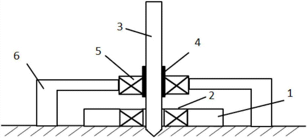
[0039] Such as figure 1 As shown, the overall structure of the electromagnetic piling in the embodiment of the present invention includes: a base 1 , a ground coil set 2 , a pile body 3 , a clamping mechanism 4 , a pile body coil set 5 , and a bracket 6 .
[0040] The base is arranged on the ground for installing the ground coil group and supporting the clamping mechanism; there is a pile hole in the middle of the base, and a groove is provided on the outer edge of the pile hole, and the ground coil group is installed in the groove (see Figure 6 ); the clamping mechanism is fixed on the base or the ground through a bracket; the clamping mechanism is used to clamp or release the pile body; The outside of the mechanism is arranged coaxially with the ground coil group, and the distance is relatively close to ensure sufficient electromagnetic force between the two coil groups.
[0041] The electromagnetic piling method includes the following steps:
[0042] (1) Fix the ground c...
Embodiment 2
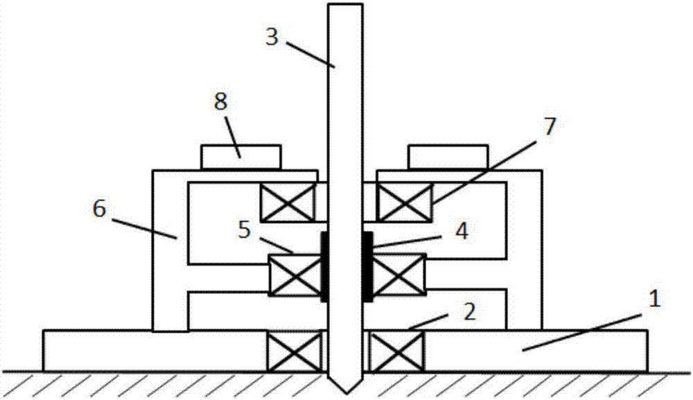
[0051] Such as figure 2 As shown, the overall structure of the electromagnetic piling of the embodiment of the present invention includes: a base 1, a ground coil group 2, a pile body 3, a clamping mechanism 4, a pile body coil group 5, a bracket 6, a first auxiliary coil group 7, and Weight 8.
[0052] The electromagnetic piling method includes the following steps:
[0053] (1) Fix the ground coil set 2 on the base 1 by bolts.
[0054] (2) The first auxiliary coil group 7 is fixed on the stand 6 by bolts, and the counterweight 8 is installed on the support 6 .
[0055] (3) Pass the pile body 3 through the first auxiliary coil group 7 and place it in the aperture of the coil group 7 .
[0056] (4) Hold the clamping mechanism 4 tightly to the pile body 3 , and the pile body coil group 5 is fastened to the pile body 3 through the clamping mechanism 4 .
[0057] (5) The clamping mechanism 4 realizes its own free movement up and down through the guide rail on the bracket 6 . ...
Embodiment 3
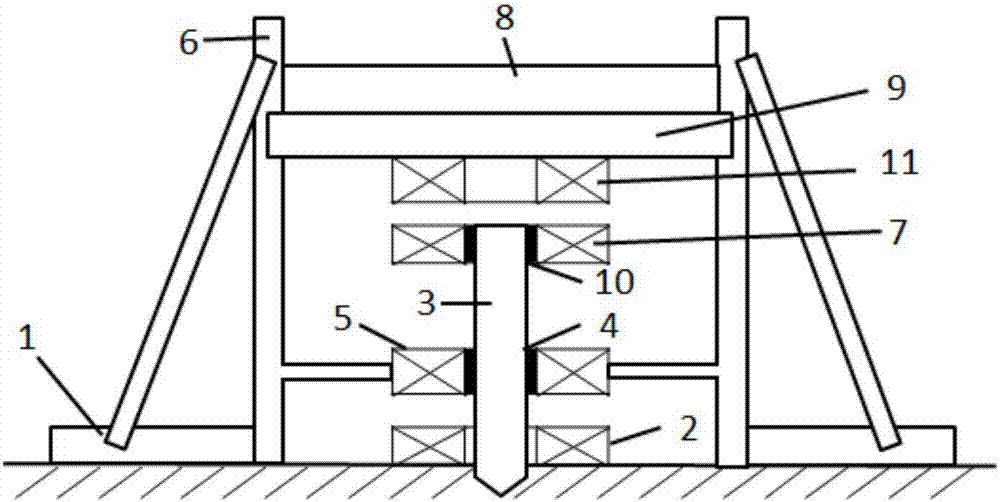
[0064] Such as image 3 As shown, the overall structure of the electromagnetic piling of the embodiment of the present invention includes: a base 1, a ground coil group 2, a pile body 3, a clamping mechanism 4, a pile body coil group 5, a bracket 6, a first auxiliary coil group 7, and Weight 8, top plate 9, second clamping mechanism 10, second auxiliary coil group 11.
[0065] The electromagnetic piling method includes the following steps:
[0066] (1) Fasten the first auxiliary coil group 7 to the pile body 3 through the second clamping mechanism 10 .
[0067] (2) Adjust the second auxiliary coil set 11 directly above the first auxiliary coil set 7 through the top plate 9 and the bracket 6 , and the top plate 9 is used to fix the second auxiliary coil set 11 .
[0068] (3) After the position adjustment of the second auxiliary coil group 11 is completed, the counterweight 8 is placed on the top plate 9 .
[0069] (4) In the piling process, the second auxiliary coil group 11...
PUM
 Abstract
Description
Claims
Application Information
 - R&D
- Intellectual Property
- Life Sciences
- Materials
- Tech Scout
- Unparalleled Data Quality
- Higher Quality Content
- 60% Fewer Hallucinations
Browse by: Latest US Patents, China's latest patents, Technical Efficacy Thesaurus, Application Domain, Technology Topic, Popular Technical Reports.
© 2025 PatSnap. All rights reserved.Legal|Privacy policy|Modern Slavery Act Transparency Statement|Sitemap|About US| Contact US: help@patsnap.com


