Impacting type ice driller
A technology for drilling ice and racks, which is applied in the directions of drilling equipment, ice drilling, earthwork drilling and mining, etc. It can solve the problems of axial reciprocating movement, inability to impact up and down, poor ice drilling effect, etc., and achieves reasonable structure and improved use. Long life and good ice drilling effect
- Summary
- Abstract
- Description
- Claims
- Application Information
AI Technical Summary
Problems solved by technology
Method used
Image
Examples
Embodiment 1
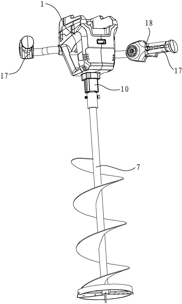
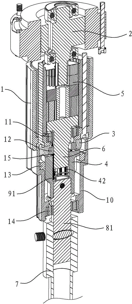
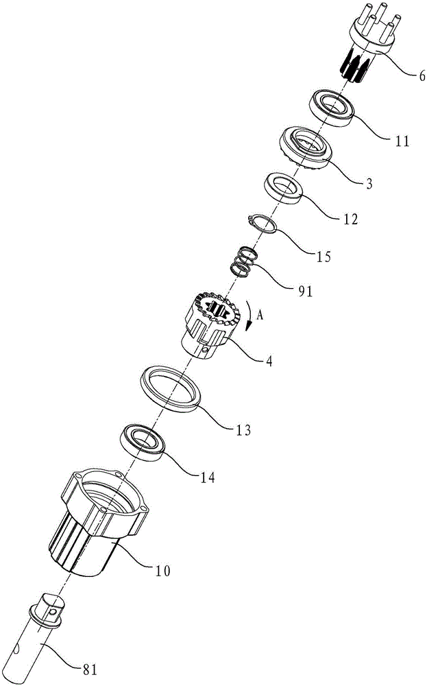
[0030] like Figure 1 to Figure 5 As shown, the impact ice drilling machine in this embodiment includes a frame 1, a motor 2, a fixed ratchet 3, a rotating ratchet 4, a coupling 5, a spline shaft 6, a drill rod 7, a first connecting shaft 81, a second Main components such as a compression spring 91, limit cylinder 10, first axle sleeve 11, second axle sleeve 12, third axle sleeve 13, fourth axle sleeve 14, fixed washer 15 and handle 17.
[0031] The motor 2 is installed on the frame 1, and the output shaft of the motor 2 is connected with the upper end of the spline shaft 6 through a coupling 5. The fixed ratchet 3 , the rotating ratchet 4 and the spline shaft 6 are coaxially arranged, and the fixed ratchet 3 is located above the rotating ratchet 4 . The fixed ratchet 3 is fixed to the frame 1, the first shaft sleeve 11 is installed above the fixed ratchet 3, the second shaft sleeve 12 is installed inside the fixed ratchet 3, and the spline shaft 6 passes through the first sh...
Embodiment 2
[0039] like Figure 6 to Figure 8 As shown, the installation structure of the fixed ratchet and the rotating ratchet of the impact type ice drilling machine in this embodiment is different from that in Embodiment 1. In this embodiment, the rotating ratchet 4 and the fixed ratchet 3 are coaxially arranged and located at the center of the fixed ratchet 3. Below, and the axial direction of the fixed ratchet 3 and the rotating ratchet 4 is parallel to the axial direction of the spline shaft 6 . The connection plate 16 is fixed on the frame 1 , and the connection plate 16 is provided with a first installation hole 161 and a second installation hole 162 adjacently arranged. The fixed ratchet 3 is installed in the first mounting hole 161, the rotating ratchet 4 is located under the connecting plate 16, the outer peripheral wall of the rotating ratchet 4 is formed with an external keyway 43, and the spline shaft 6 passes through the second mounting hole 162 downwards, and The part pr...
PUM
 Abstract
Description
Claims
Application Information
 - R&D
- Intellectual Property
- Life Sciences
- Materials
- Tech Scout
- Unparalleled Data Quality
- Higher Quality Content
- 60% Fewer Hallucinations
Browse by: Latest US Patents, China's latest patents, Technical Efficacy Thesaurus, Application Domain, Technology Topic, Popular Technical Reports.
© 2025 PatSnap. All rights reserved.Legal|Privacy policy|Modern Slavery Act Transparency Statement|Sitemap|About US| Contact US: help@patsnap.com


