
In-situ cast-in-place concrete stubble on shaft wall and its supporting formwork device and construction method

A concrete formwork and concrete technology, which is used in shaft equipment, earthwork drilling, wellbore lining, etc., can solve the problems of long construction time, weak connection, and difficult construction, and achieves improved well completion speed, stable and firm structure, and construction speed. quick effect

Active Publication Date: 2018-04-24
安徽马钢矿业资源集团姑山矿业有限公司 +1
View PDF5 Cites 0 Cited by
  • Summary
  • Abstract
  • Description
  • Claims
  • Application Information

AI Technical Summary

Problems solved by technology

The disadvantages are that the structure of the device is complex and the construction is difficult; it is labor-intensive and time-consuming, and the construction time is long, which seriously restricts the speed of well completion; since the upper and lower concrete joints still use the same grade of concrete and there is no connecting member, the formwork at the bottom of the construction process It is easy to deform and has no external extrusion support, and the concrete stubble still has the disadvantages of weak connection and internal structure, and the overall quality cannot be guaranteed, especially in the deep formation where the water pressure is high. and sealing and waterproofing problems have not been well resolved

Method used


Image

  • In-situ cast-in-place concrete stubble on shaft wall and its supporting formwork device and construction method
  • In-situ cast-in-place concrete stubble on shaft wall and its supporting formwork device and construction method
  • In-situ cast-in-place concrete stubble on shaft wall and its supporting formwork device and construction method

Examples


Embodiment Construction

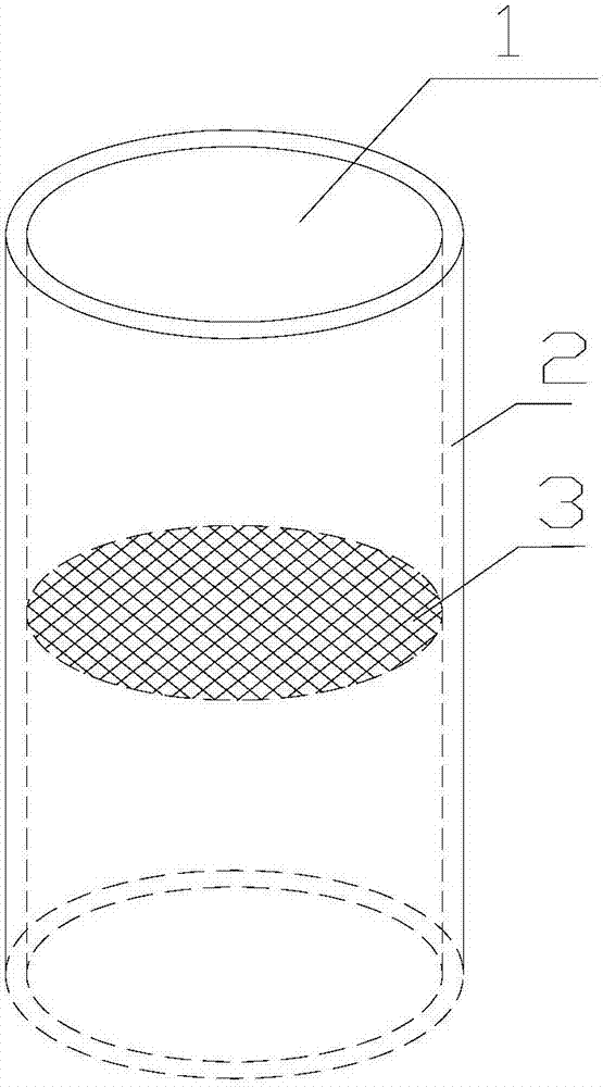
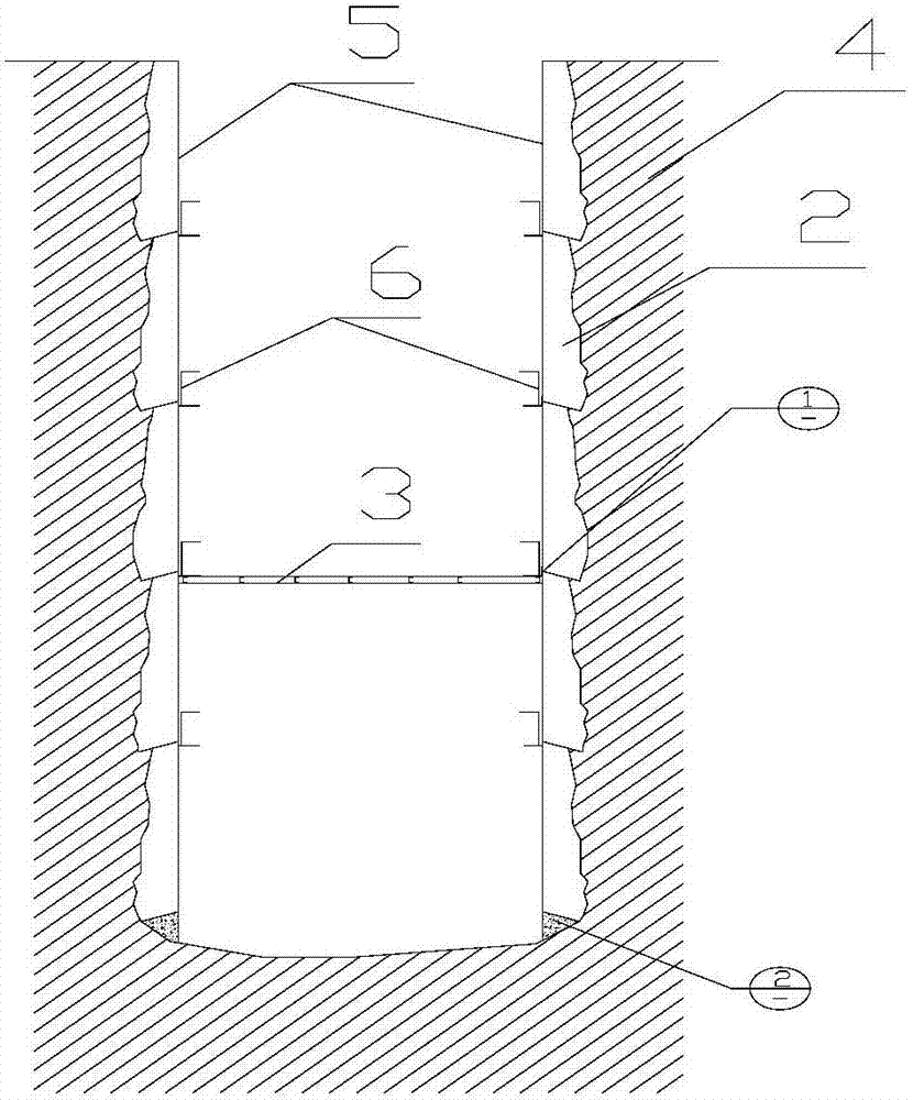
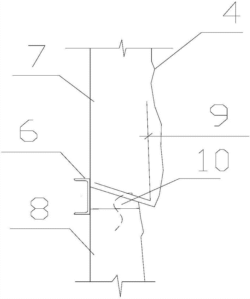
[0033] Depend on figure 1 , figure 2 , image 3 , Figure 4 , Figure 5 , Figure 6 It can be seen that the stubble of the cast-in-place concrete on the shaft wall, including the shaft wall concrete 2, is poured into the shaft 1 in sections, which is characterized in that the joint of the upper and lower shaft wall concrete is provided with a stubble joint, and the lower end of the upper shaft wall concrete 7 is provided with a connecting steel mesh 9 , is connected with the lower shaft wall concrete 8; the two wings of the connecting steel mesh 9 are in an "L" shape, when pouring the upper shaft wall concrete 7, the vertical wings are arranged in the upper shaft wall concrete, and the horizontal wings are placed in the upper shaft wall concrete formwork The lower end with a bevel; before pouring the lower shaft wall concrete 8, straighten the horizontal wing and extend into the upper part of the cavity formed by the preset shaft wall concrete formwork 5 and the surroundi...


PUM


Abstract

The invention relates to a vertical shaft wall cast-in-place concrete joint and a formwork device and a and construction method of the vertical shaft wall cast-in-place concrete joint, and belongs to the field of underground mine concrete building structures. The vertical shaft wall cast-in-place concrete joint is characterized in that a joint seam is formed at a jointing position of shaft wall concrete at the upper section and shaft wall concrete at the lower section, a connecting reinforcement net with two L-shaped wings are arranged at the lower end of the shaft wall concrete at the upper section, the shaft wall concrete at the upper section and the shaft wall concrete at the lower section are connected, and a transverse wing of the connecting reinforcement net is straightened to extend into the upper portion of the shaft wall concrete at the lower section; a joint formwork is arranged on the outer side of the joint seam of the shaft wall concrete at the upper section and the shaft wall concrete at the lower section, joint concrete is poured into a cavity defined by the joint formwork, surrounding rock, the shaft wall concrete at the upper section and the shaft wall concrete at the lower section in an extrusion manner, and is tightly and firmly connected with the shaft wall concrete at the upper section, the shaft wall concrete at the lower section and the surrounding rock together; and the formwork device is composed of arc-shaped joint formworks in a certain number, a wood formwork, a wooden wedge and a pressing mechanism. The vertical shaft wall cast-in-place concrete joint has the beneficial effects that the conception is simple, manufacturing is simple, the structure is firm, installation is convenient, construction is rapid, repeated utilization can be achieved, the joint concrete molding whole is dense and smooth, the intensity is high, the shaft space is not occupied, shaft construction can be continuously carried out, and the well completion speed is high.

Description

technical field [0001] The invention belongs to the technical field of concrete building structures in underground mines, and in particular relates to stubble splicing of cast-in-place concrete on shaft walls, formwork support devices for stubble splicing construction, and stubble splicing construction methods. Background technique [0002] The vertical shaft is the most important project in the underground mining mine, responsible for lifting, transportation, ventilation, drainage and safe passage of personnel. Most shaft shafts adopt circular cross-section. According to different technological layout requirements, the diameter of the shaft varies, and the thickness of the shaft wall is not less than 300mm. Reinforced concrete and concrete support structure. In recent years, with the application of large metal templates, the shaft of the shaft is cast in sections, and the height of each section is not less than 3000mm. While the construction of the shaft is getting faster a...

Claims


Application Information

Patent Timeline
Patent Type & Authority Patents(China)
IPC IPC(8): E21D5/11E21D5/12
CPCE21D5/11E21D5/12
Inventor 董亚宁
Owner 安徽马钢矿业资源集团姑山矿业有限公司
Learn More