
Device for cutting material sheets

A technology of equipment and cutting strips, which is applied in the manufacture of rigid/semi-rigid containers, paper/cardboard containers, container manufacturing machinery, etc., can solve problems such as cost, and achieve the effects of saving tool replacement, improving production efficiency, and increasing service life

Inactive Publication Date: 2016-06-22
KOLBUS
View PDF1 Cites 4 Cited by
  • Summary
  • Abstract
  • Description
  • Claims
  • Application Information

AI Technical Summary

Problems solved by technology

In particular, correcting the produced geometries and producing the same simple cut-outs that differ only in their dimensions becomes extremely costly

Method used


Image

  • Device for cutting material sheets
  • Device for cutting material sheets

Examples


Embodiment Construction

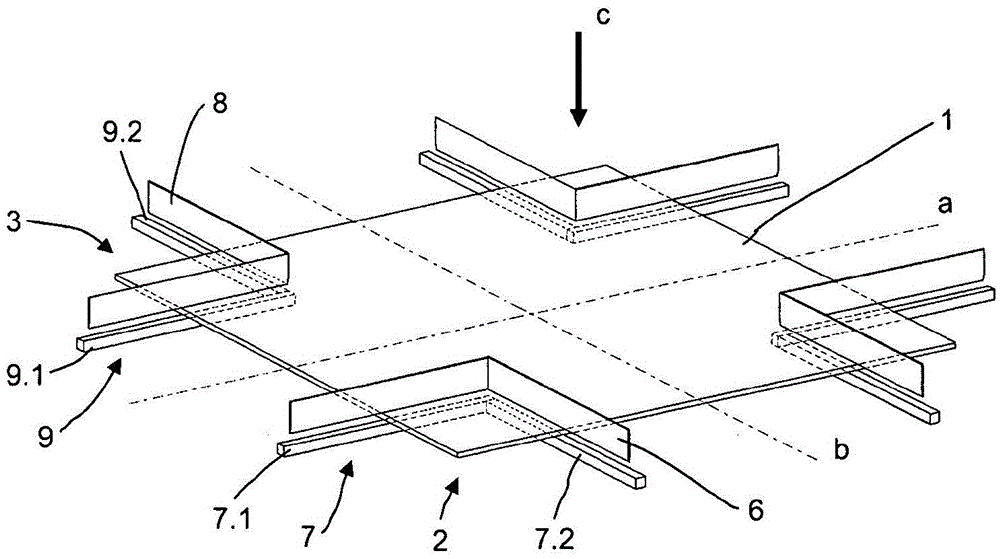
[0020] The cutting chamber of the device comprises four identical cutting units 4 each comprising a knife 6, 8 with a right-angle profile and a cutting bar 7, 9 arranged at right angles to each other and having a square transverse profile. Subsections 7.1 and 7.2 or 9.1 and 9.2 of the section. figure 1 The layout of the tool is shown, in which the corners of the tool point in each case into the entire material sheet 1 and in each case a partial leg of two opposing knives 6 , 8 is oriented coaxially. The sub-legs of the knives 6, 8 and correspondingly associated cutting elements 7, 9 protrude over the entire sheet of material 1, so that each cutting unit 4 cuts out a rectangular area 2, 3 in each case, resulting in a cross-shaped cut pieces. Such a tool configuration is suitable, for example, for cutting off corner regions of cardboard or box lids cut into a cross-recess shape, which can be further processed into dimensionally stable boxes.

[0021] figure 2 One of four cut...


PUM


Abstract

A device for cutting plane material sheets (1) to a sectionally concave contour by separating several discontiguous sections (2, 3), with at least two cutting units (4) that respectively feature a knife (6, 8) and a cutting bar (7, 9) and can be positioned relative to one another by adjusting devices (11, 12, 13, 14) such that format adjustments and corrections can be realized without tool change.

Description

technical field [0001] The invention relates to a device for cutting an unfolded whole sheet of material according to the preamble of claim 1 . Background technique [0002] For the cutting of entire sheets of material into partially concave contours, for example for use as folding box blanks, devices are known which produce the desired contour entirely in a single cutting process. For this purpose, the device comprises a work table, arranged above which the cutting material lies flat, and a cutting tool which is lowered onto the work table and at the same time with vertical parallel knives Cutting separates entire sheets of material. The tools comprise profile cutters fixed on a base plate and are each individually manufactured according to the desired cutting profile. [0003] In order to keep the production of the tool simple, the profile tool is bent from spring strip steel and is embedded in a wooden board or cast into a plastic holder for shape retention, wherein the...

Claims


Application Information

Patent Timeline
IPC IPC(8): B31B1/20B31B50/02B31B50/16B31B50/20B31B50/25
CPCB26D1/06B26D3/14B26D7/015B26F1/38B26D2001/0033B26D2001/0066B26D1/045B26D5/02
Inventor R·彼得斯T·罗尔芬
Owner KOLBUS
Learn More