
Combined drill molding milling cutter and manufacturing method thereof

A technology for forming milling cutters and manufacturing methods, applied in milling cutters, manufacturing tools, drilling and other directions, can solve problems such as size mismatch, and achieve the effect of simplifying processing procedures, reducing the risk of rework or scrapping, and having high precision

Inactive Publication Date: 2016-06-22
GUANGZHOU JUNJIE PRECISION TOOLS CO LTD
View PDF7 Cites 5 Cited by
  • Summary
  • Abstract
  • Description
  • Claims
  • Application Information

AI Technical Summary

Problems solved by technology

[0003] The embodiment of the present invention discloses a compound drill forming milling cutter and a manufacturing method thereof, which can solve the problem of simplifying the processing procedures of flange rivet holes and valve seat forming holes, and avoid that the chamfering of the chamfering knife is different from the size of the hole of the ordinary drill bit. Matching issues to reduce the risk of rework or scrap

Method used


Image

  • Combined drill molding milling cutter and manufacturing method thereof
  • Combined drill molding milling cutter and manufacturing method thereof
  • Combined drill molding milling cutter and manufacturing method thereof

Examples


Embodiment 1

[0036] Please refer to figure 1 , figure 1 It is a structural schematic diagram of a composite drill forming milling cutter disclosed in an embodiment of the present invention. Such as figure 1 As shown, the compound drill form milling cutter can include:

[0037]The shank 1 and the drill body 2, wherein the shank 1 and the drill body 2 are cylindrical structures, the diameter of the shank 1 is larger than the diameter of the drill body 2, and the lower end of the shank 1 is coaxially connected with the upper end of the drill body 2, The lower end of the drill body 2 is coaxially connected with the upper end of the transition section 3 of the cylindrical structure, and the diameter of the transition section 3 is smaller than the diameter of the drill body 2; The other water end surface of the table 4 is coaxially connected with the upper end of the drill section 5 of the cylindrical structure, and the lower end of the drill section 5 shrinks into a drill structure 51; The ...

Embodiment 2

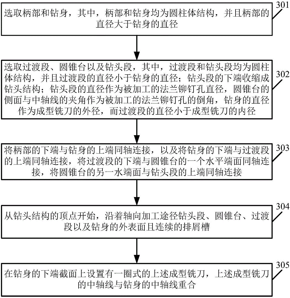
[0049] Please refer to image 3 , image 3 It is a schematic flowchart of a manufacturing method of a compound drill forming milling cutter disclosed in an embodiment of the present invention. Such as image 3 Shown, the manufacture method of this compound drill form milling cutter can comprise the following steps:

[0050] 301. Select the shank and the drill body, wherein both the shank and the drill body are cylindrical structures, and the diameter of the shank is larger than the diameter of the drill body;

[0051] 302. Select the transition section, the truncated cone and the drill section, wherein the transition section and the drill section are cylindrical structures, and the diameter of the transition section is smaller than the diameter of the drill body; the lower end of the drill section shrinks into a drill structure; the diameter of the drill section is as The diameter of the processed flange rivet hole, the angle between the side of the truncated cone and the c...


PUM


Abstract

The invention discloses a combined drill molding milling cutter and a manufacturing method thereof. The combined drill molding milling cutter comprises a handle part and a drill body which are both in a cylinder structure, wherein the diameter of the handle part is larger than the diameter of the drill body; the handle part, the drill body and a transition section in a cylinder structure are sequentially and coaxially connected; the diameter of the transition section is smaller than the diameter of the drill body; the transition section, a cone frustum and a drill bit section in a cylinder structure are sequentially and coaxially connected; the lower end of the drill bit section is contracted into a drill bit structure; the diameter of the drill bit section is taken as the diameter of a processed flange rivet hole; an included angle formed by the side of the cone frustum and a central axis is taken as a chamfer of the processed flange rivet hole; the diameter of the drill body serves as the outer diameter of the molding milling cutter; however, the diameter of the transition section is smaller than the inner diameter of the molding milling cutter; the drill bit section, the cone frustum, the transition section and a continuous chip groove in the surface of the drill body are arranged from the peak of the drill bit structure along the axial processing route; a coil type molding milling cutter is arranged on the section of the lower end of the drill body; and the central axis of the molding milling cutter and the central axis of the drill body are overlapped. The processing procedures for the flange rivet hole and a valve seat molding hole are simplified.

Description

technical field [0001] The invention relates to the technical field of precision machining, in particular to a compound drill forming milling cutter and a manufacturing method thereof. Background technique [0002] In the process of air-conditioning compressor bearing flange rivet holes and valve seat forming holes, the traditional method is to use independent ordinary drills and forming milling cutters to process flange rivet holes and valve seat forming holes respectively, and then use a chamfer The knife is used to process the chamfer of the flange rivet hole. In practice, it is found that in the process of processing the flange rivet holes and the valve seat forming holes, the processing devices need to be replaced frequently, resulting in many shortcomings such as complex processing procedures and cumbersome processing; in addition, due to the chamfering process of the flange rivet holes and the There are positioning errors in the drilling process. Using separate devic...

Claims


Application Information

Patent Timeline
Patent Type & Authority Applications(China)
IPC IPC(8): B23B51/08B23C5/10
CPCB23B51/08B23B2251/242B23C5/10B23C2210/242B23C2210/247
Inventor 黄展莫傲然颜东波
Owner GUANGZHOU JUNJIE PRECISION TOOLS CO LTD
Learn More