
Method and device for encoding spatiotemporal signals

A space-time signal and signal technology, applied in the field of information coding, can solve the problems of high cost of acquisition and processing circuit design, increased pixel size, and impossibility

Active Publication Date: 2019-01-18
SPIKE VISION (BEIJING) TECHNOLOGY CO LTD
View PDF6 Cites 0 Cited by
  • Summary
  • Abstract
  • Description
  • Claims
  • Application Information

AI Technical Summary

Problems solved by technology

However, such a video frame rate cannot represent faster-changing physical phenomena, so high-frequency cameras have appeared, and their frame rates can reach 1,000 frames per second or even 10,000 frames or even higher. The problem brought about is the large amount of data. As the scale increases, the corresponding collection and processing circuit design is expensive or even impossible. More importantly, the increase in the frame rate means that the exposure time of a single frame is reduced, and the exposure of a single frame image collected is seriously insufficient. The way to make up for it is to increase pixel size, which in turn brings about a reduction in spatial resolution

Method used


Image

  • Method and device for encoding spatiotemporal signals
  • Method and device for encoding spatiotemporal signals

Examples


Embodiment 1

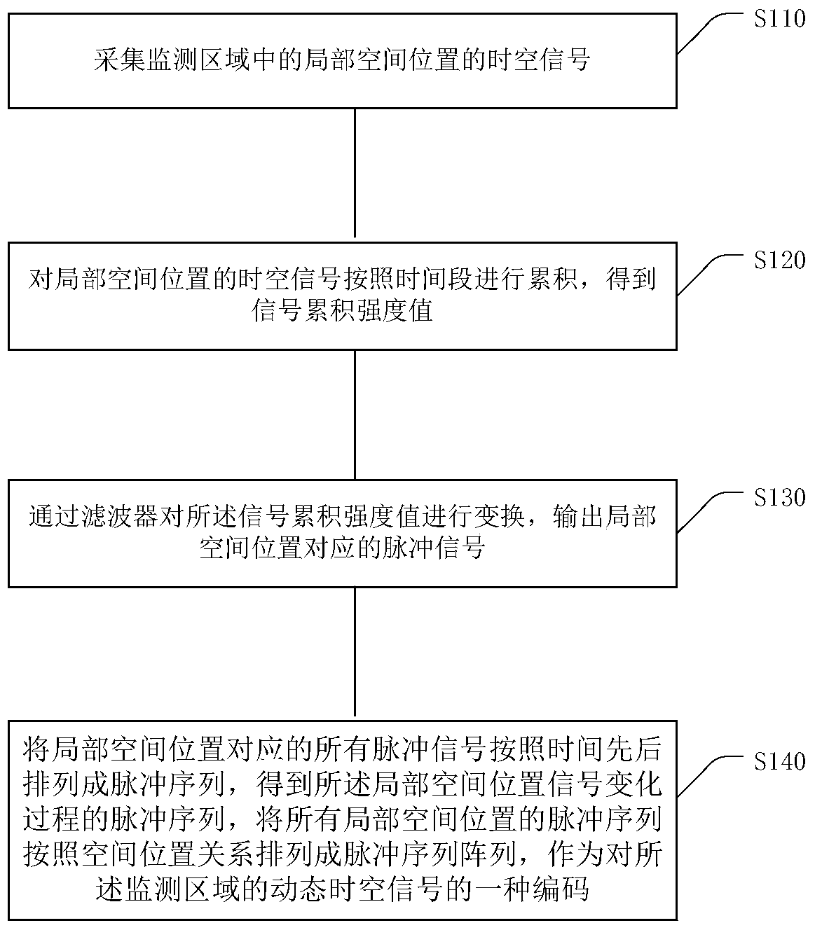
[0074] In order to fundamentally solve the problem of high-efficiency coding of space-time signals such as video, the present invention proposes a new solution from two levels of video representation and coding methods. Different from the method of representing dynamic images as image sequences (the "image" here is also referred to as "frame") since the appearance of film and television, the present invention first converts the signal change of each local spatial position (for an image, it is a pixel's The change process) is coded separately in time order. For dynamic images, this time series signal is called "pixel stream", and then the sequence matrix composed of time series signals is spatially encoded according to the spatial sparsity. It should be noted that although multiple pixel streams are still arranged in an array according to the relative spatial position, the pixel streams do not perform equal interval sampling and "frame-level alignment" like traditional video, bu...

Embodiment 2

[0120] This embodiment provides a device for encoding spatio-temporal signals, the specific implementation structure of the device is as follows figure 2 As shown, specifically, the following modules may be included: a signal collector 21, a signal accumulator 22 and a filter 23;

[0121] The signal collector is used to collect the spatio-temporal signals of each local spatial position in the monitoring area, and transmit the spatio-temporal signals to the signal accumulator;

[0122] The signal accumulator is used for accumulating spatio-temporal signals at local spatial positions according to time to obtain a signal cumulative strength value, and transmitting the signal cumulative strength value to the filter;

[0123] The filter is used to transform the cumulative intensity value of the signal, and output a pulse signal when the transformed result exceeds a specific threshold;

[0124] Arranging the pulse signals corresponding to the local spatial positions into a sequenc...


PUM


Abstract

Embodiments of the present invention provide a method and device for encoding space-time signals. The method includes: collecting the spatio-temporal signals of each local spatial position in the monitoring area, and accumulating the spatio-temporal signals according to time to obtain the signal cumulative intensity value; transforming the signal cumulative intensity value through a filter, and outputting when the transformed result exceeds a specific threshold Pulse signal; arrange the pulse signals corresponding to the local spatial positions into a sequence according to time, and obtain the pulse sequence expressing the local spatial position signal and its change process; arrange the pulse sequences of all local spatial positions into a pulse sequence array according to the spatial position relationship , as the encoding of the dynamic spatio-temporal signal of the monitored area. The embodiment of the present invention performs pulse coding in the time domain first, and then performs spatial coding according to the spatial position, fully retains the time domain and spatial domain information, not only can reconstruct the static image at any time, but also retains the fine motion of the high-speed moving scene process.

Description

technical field [0001] The present invention relates to the technical field of information coding, in particular to a method and device for coding space-time signals. Background technique [0002] The form that exists in a certain time and space is the source of information. For example, the propagation of light in space forms a dynamic image, the flow of a large number of water molecules produces ocean information, and the dynamic movement of air molecules and other floating objects forms climate information. As far as dynamic images are concerned, humans and creatures perceive the world by capturing photons through their eyes. Modern cameras use CCD (Charge-coupled Device, charge-coupled device) or CMOS ((Complementary Metal Oxide Semiconductor, Complementary Metal Oxide Semiconductor) to capture photons to record The dynamically changing world produces a large amount of image and video data. [0003] Traditional methods of expressing moving images are two-dimensional ima...

Claims


Application Information

Patent Timeline
Patent Type & Authority Patents(China)
IPC IPC(8): H04N19/107H04N19/503H04N19/593H04N19/31H04N19/33
CPCH04N19/107H04N19/31H04N19/33H04N19/503H04N19/593G06T9/002H04N19/62G06V20/52G06V10/449H04N19/15H04N19/159H04N19/85H04L1/0625H04L1/0675
Inventor 黄铁军
Owner SPIKE VISION (BEIJING) TECHNOLOGY CO LTD
Learn More