A self-powered device for wireless sensor nodes

A wireless sensor node, self-powered technology, applied in circuit devices, battery circuit devices, wind power generation, etc., can solve the problems of reduced power generation, large workload, small size of the device, etc., to improve power generation, attitude self-recovery , The effect of strong damage resistance

Active Publication Date: 2017-11-17
BEIJING INSTITUTE OF TECHNOLOGYGY
View PDF7 Cites 5 Cited by
  • Summary
  • Abstract
  • Description
  • Claims
  • Application Information

AI Technical Summary

Problems solved by technology

The volume of the devices in practical applications is relatively small. After miniaturization, the volumes of wind turbines and solar panels are greatly compressed. It is difficult to ensure the area of ​​solar panels and the capacity of vertical axis fans while meeting the miniaturization requirements of wireless sensor nodes. Ventilation, the overall power generation of the device will drop significantly and even make it difficult to maintain the normal work of wireless sensor nodes
In addition, the overall structure is a cuboid, which cannot be deployed
When the device is subjected to external force and changes its posture, it cannot restore itself to a normal working posture
In order to ensure that the sensor nodes are in the correct posture, the bottom surface of each node needs to be fixed when deploying the nodes, and the workload is too large
Fixed nodes lose the flexibility of wireless sensor networks at the same time, and are not practical and feasible when widely deploying wireless sensor networks

Method used


Image

  • A self-powered device for wireless sensor nodes
  • A self-powered device for wireless sensor nodes
  • A self-powered device for wireless sensor nodes

Examples


Embodiment Construction

[0038] The present invention will be described in detail below with reference to the accompanying drawings and examples.

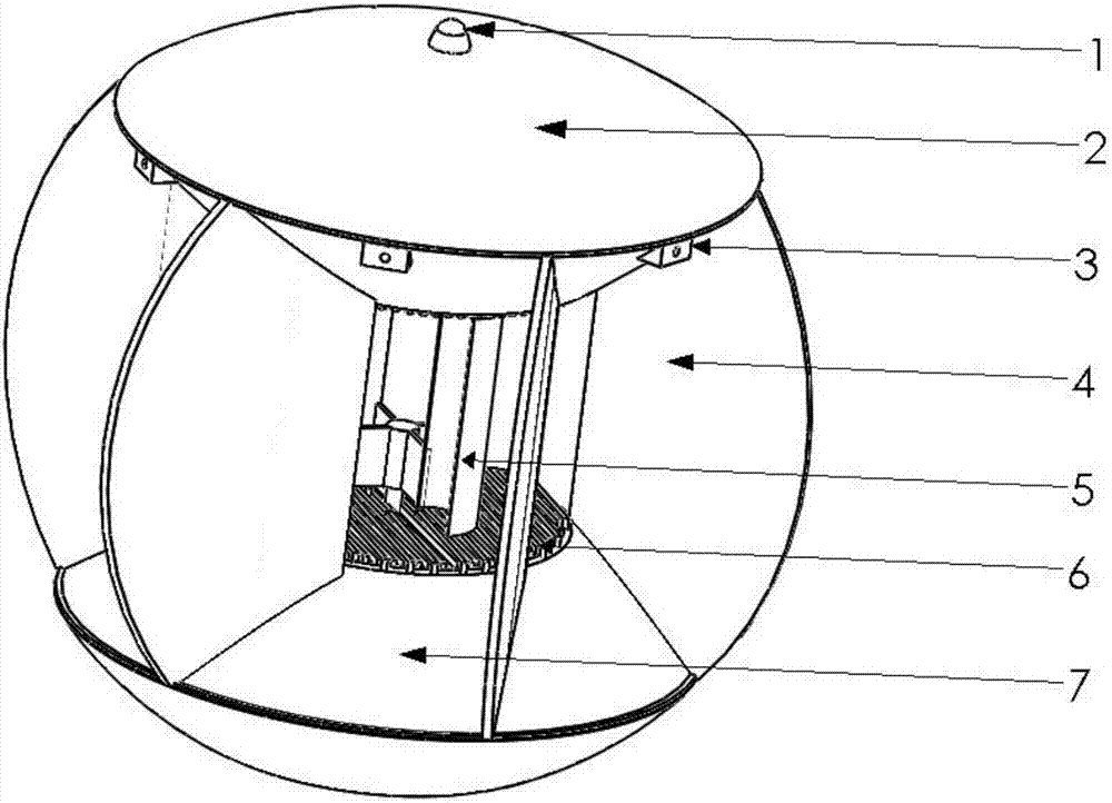
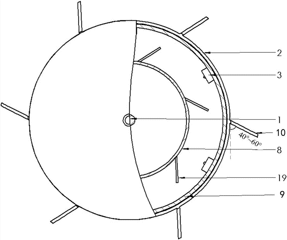
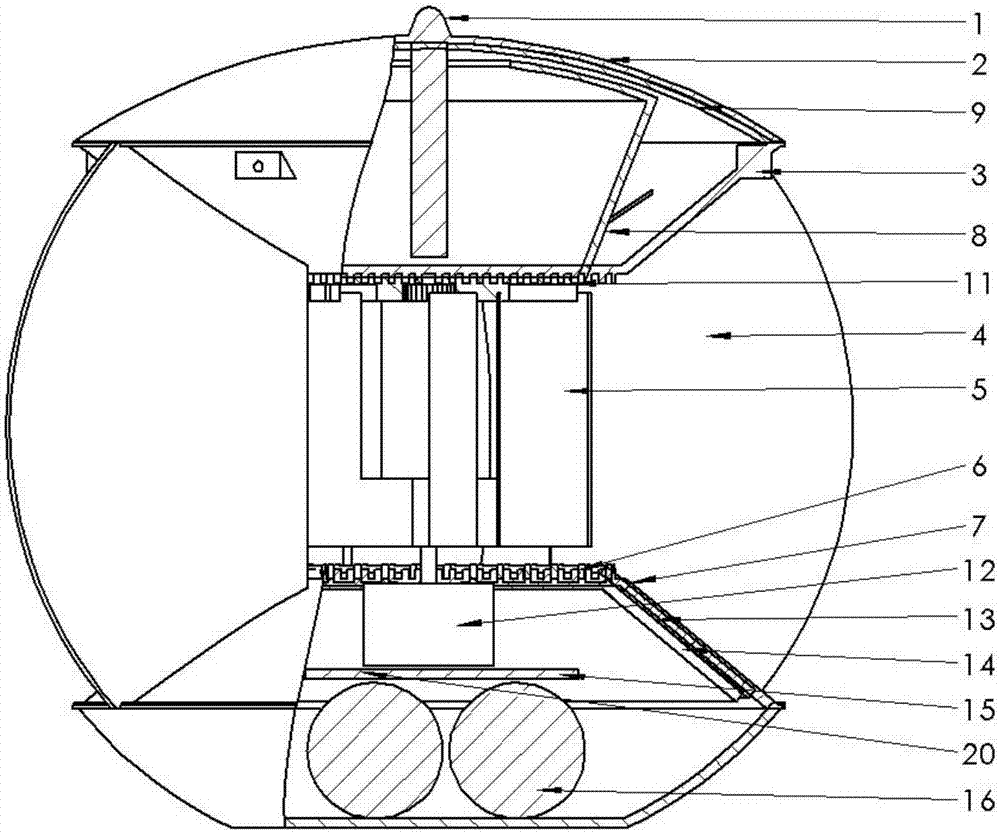
[0039] The present invention provides a self-powered device for wireless sensor nodes, such as figure 1 As shown, it includes an antenna 1, a large solar panel 2 on the top, several sensors 3, a vertical axis wind turbine 5, an air collection device composed of 6 air duct openings 4, and 6 air ducts Small solar panel 7 on the bottom side, 2 heat sinks 8 and 14, thermoelectric power generation sheets 9 and 13 on the back of the 2 solar panels, power control module 15, energy storage module 16 and sensor data processing module 20.

[0040] It can be seen from the figure that the whole device is like a sphere with the bottom cut off. The sphere skeleton acts as a support, and the device may bear certain external forces during deployment and work, and all device components are installed inside the sphere, so the sphere skeleton needs to have sufficient streng...


PUM


Abstract

The invention discloses an automatic power-supply apparatus for wireless sensing nodes. By adoption of the automatic power-supply apparatus, solar energy, wind energy and temperature difference can be comprehensively utilized, and the miniaturization of the apparatus can be satisfied. The automatic power-supply apparatus adopts a spherical framework; the automatic power-supply apparatus comprises a dome-shaped top cover and a bottom plate; multiple air guiding sheets are uniformly and vertically mounted between the top cover and the bottom plate; top solar cell panels are arranged on the upper surface of the top cover; top temperature-difference power generation chips are mounted on the back surfaces of the top solar cell panels; a perpendicular wind power generator is mounted in the middle of the spherical framework; the air guiding sheets, the lower surface of the top cover and the upper surface of the bottom plate form air channels; air channel opening solar cell panels are mounted on the lower surfaces of the air channels; and bottom temperature-difference power generation chips are arranged on the back surfaces of the air channel opening solar cell panels. Therefore, solar energy, wind energy and temperature difference are fully utilized to supply power supply to sensors; and meanwhile the automatic power-supply apparatus is compact in structure.

Description

technical field [0001] The invention relates to the technical field of wireless sensors, in particular to a self-powered device for wireless sensor nodes. Background technique [0002] The wireless sensor network is composed of a large number of sensor nodes deployed in the monitored area, and the nodes communicate with each other to form a self-organized network system. Each sensor node is a microsystem that integrates functions such as information collection, data processing and wireless communication. [0003] Wireless sensor networks have the characteristics of a large number of nodes, wide distribution areas, and complex or dangerous deployment environments. Some areas are even inaccessible to personnel. Therefore, it is unrealistic to replenish energy by manually replacing batteries and charging them. When the carried energy is exhausted, the sensor nodes will not be able to complete the scheduled tasks, which greatly limits the popularization and application of senso...

Claims


Application Information

Patent Timeline
Patent Type & Authority Patents(China)
IPC IPC(8): H02J7/35F03D3/00F03D3/06
CPCF03D3/00F03D3/06H02J7/35Y02E10/74Y02E10/76
Inventor 邓方吕建耀陈杰关胜盘李佳洪桂鹏郝群邱煌彬谢炜
Owner BEIJING INSTITUTE OF TECHNOLOGYGY
Why Eureka
Try Eureka