Mobile substation

A technology for moving substations and cables, applied in the field of substations, can solve the problems of local high temperature, transformer outage, and high temperature, and achieve the effects of weakening damage, effective temperature control, and long service life

Active Publication Date: 2016-06-15
TRANSFORMER CO LTD SHANDONG TAISHAN
View PDF5 Cites 3 Cited by
  • Summary
  • Abstract
  • Description
  • Claims
  • Application Information

AI Technical Summary

Problems solved by technology

[0002] As the power supply equipment for the production machinery in the working face of the underground mining area, the safe and stable operation of the mobile substation in the coal mine is a necessary condition for the reliable operation of the working face of the entire mining area. Once a failure occurs, it will cause serious consequences, not only affecting production, but also causing personal accidents. The working environment of the mobile substation is humid, the temperature is high, and there is a lot of dust. The structure of the internal tap changer is complex, and it is frequently operated for switching. The main fault occurs in the head part, which directly affects the normal operation of the transformer. Influenced by materials, it is very easy to oxidize the surface of the head, and the high temperature will cause the spring to fail, and there will be oil film or dust between the moving and static contacts, which will increase the resistance of the poor contact between the contacts, cause local high temperature, damage the contact surface and cause the transformer to stop operating, so There is a need for a mobile substation that can work in harsh underground environments for a long time, and there is an urgent need for a mobile substation that can ensure moisture-proof, dust-proof, explosion-proof, and effective temperature control

Method used


Image

  • Mobile substation
  • Mobile substation

Examples


Embodiment Construction

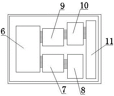
[0013] Such as Figure 1-2 In the shown embodiment, a mobile substation includes a sealed steel shell 1 and an arc-shaped shell 2. The inside of the sealed steel shell 1 is filled with a positive pressure of 0.02-0.03Mpa through a liquid nitrogen gas filling tank 12, and the circle The arc-shaped shell 2 is welded on the upper end of the airtight steel shell 1, and the inside of the airtight steel shell 1 is provided with a sound-insulating and moisture-proof inner panel 3, and the upper end of the sound-insulating and moisture-proof inner plate 3 is equipped with an air inlet 4 and an air outlet 5. An amorphous alloy transformer 6 is installed in the sound-proof and moisture-proof inner panel 3. One end of the amorphous alloy transformer 6 is connected to the high-voltage incoming and outgoing line cabinet 7 through a cable, and the high-voltage incoming and outgoing line cabinet 7 is connected to the high-voltage chamber 8 through a cable. The amorphous alloy transformer The...


PUM


Abstract

A mobile substation comprises a sealing steel shell body and an arc shell, wherein positive pressure of 0.02-0.03MPa is filled to the interior of the sealing steel shell body through liquid nitrogen inflation, the arc shell is welded at the upper end of the sealing steel shell body, a sound insulation and moisture prevention inner plate is arranged inside the sealing steel shell body, an air inlet and an air outlet are arranged at the upper end of the sound insulation and moisture prevention inner plate, an amorphous alloy transformer is arranged in the sound insulation and moisture prevention inner plate, a positive pressure inflation device is arranged inside the sealing steel shell body and comprises an air inlet, an air outlet, a liquid nitrogen inflation tank and valves, the liquid nitrogen inflation tank is connected with the air inlet, the valves are separately arranged on the air inlet and the air outlet and are connected with a programmable logic controller (PLC) through wires, and the PLC is connected with a temperature connector through a wire. By the mobile substation, the effects of moisture prevention, dust prevention and explosion prevention are effectively ensured, meanwhile, the temperature is effectively controlled, the mobile substation has long service lifetime and can be applicable for borehole operation for a long time.

Description

technical field [0001] The invention relates to the technical field of substations, in particular to a mobile substation. Background technique [0002] As the power supply equipment for the production machinery in the working face of the underground mining area, the safe and stable operation of the mobile substation in the coal mine is a necessary condition for the reliable operation of the working face of the entire mining area. Once a failure occurs, it will cause serious consequences, not only affecting production, but also causing personal accidents. The working environment of the mobile substation is humid, the temperature is high, and there is a lot of dust. The structure of the internal tap changer is complex, and it is frequently operated for switching. The main fault occurs in the head part, which directly affects the normal operation of the transformer. Influenced by materials, it is very easy to oxidize the surface of the head, and the high temperature will cause ...

Claims


Application Information

Patent Timeline
IPC IPC(8): H02B1/28H02B1/56
CPCH02B1/28H02B1/56
Inventor 李善军褚成鸿
Owner TRANSFORMER CO LTD SHANDONG TAISHAN
Why Eureka
Try Eureka