
Underwater camera calibration method

A camera calibration, camera technology, applied in image analysis, image enhancement, instruments and other directions, can solve the problem that the calibration accuracy cannot meet the high-precision measurement, it is regarded as a linear change, and it is difficult to achieve.

Inactive Publication Date: 2016-06-15
HARBIN INST OF TECH SHENZHEN GRADUATE SCHOOL
View PDF3 Cites 33 Cited by
  • Summary
  • Abstract
  • Description
  • Claims
  • Application Information

AI Technical Summary

Problems solved by technology

The first is a physically assisted method (SchechnerYY, KarpelN.RecoveryofUnderwaterVisibilityandStructurebyPolarizationAnalysis.IEEEJournalofOceanicEngineering, 2005,30(3):570-587), which can transfer the lens imaging center of the camera to the refraction by designing a special optical component. The refraction occurs at the plane where the underwater camera is waterproof, and then the refraction phenomenon is offset by the special shape of the optical components. good implementation
[0004] The second method is to use the auxiliary plane method for camera calibration (NarasimhanSG, NayarSK. Structured light methods for underwater imaging: lightstripes scanning and photometric stereo, OCEANS, 2005. Proceedings of MTS / IEEE. 2005: 2610-2617), by adding an auxiliary calibration plate to determine the light before incident Direction vector, use this increased known quantity to calibrate the camera parameters. Since this method requires a special calibration plate, the operation is very complicated
[0005] The third type of method is to regard the existence of refraction as a focal length change (FerreiraR, CosteiraJP, SantosJA.StereoReconstructionofaSubmergedScene.PatternRecognition&ImageAnalysis, 2005,3522:102-109.), because the extension line of the incident light will eventually intersect the optical axis of the camera at one point, Assuming that the intersection point of the extension line of the incident ray and the imaging plane is the same as the intersection point of the optical axis of the refracted ray fish, the imaging plane of the camera needs to move backward, which is equivalent to lengthening the focal length of the camera. According to Snell's law, the focal length of the camera with respect to the incident angle can be calculated Because the change is related to the incident angle of different image points, it cannot be regarded as a linear change, so this method will still bring a certain error. The larger the incident angle of the light, the imaging point on the imaging plane will be produce greater error
[0009] Most of the traditional underwater camera calibration algorithms use the method of correcting the radial distortion to eliminate the influence of the refraction plane, but this method only uses the radial distortion to approximate the influence of the refraction plane on imaging, but because different pixels have different effects of refraction , so it is impossible to correct the entire image with a uniform distortion parameter, which will bring very obvious errors
Although the method based on the physical model can calibrate higher-precision camera parameters, the model is complex and the calculation complexity is high. Some optimization algorithms require appropriate initial values, such as the distance from the camera center to the refraction plane. Calibration is very important, most methods assume that this parameter is known, but in fact it cannot be directly and accurately measured
Li Xuyong proposed a two-step underwater camera calibration method, which can calculate the distance from the optical center of the camera to the glass refraction plane, but this method uses a corresponding method for underwater refraction processing, so the calibration accuracy will be affected. certain influence
The calibration of the binocular system of underwater robots is often used in positioning or navigation, and the calibration accuracy cannot meet the requirements of high-precision measurement

Method used


Image

  • Underwater camera calibration method
  • Underwater camera calibration method
  • Underwater camera calibration method

Examples


Embodiment Construction

[0037] The present invention will be further described below in conjunction with the accompanying drawings.

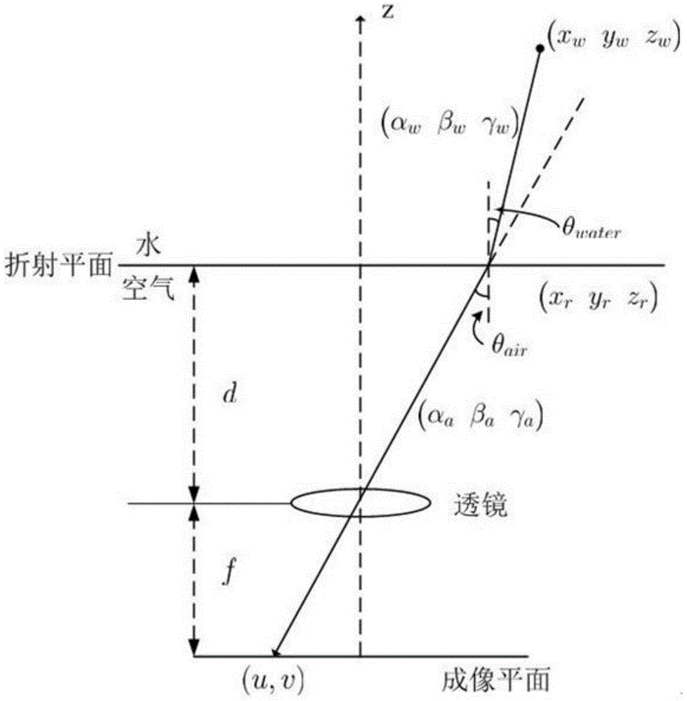
[0038] A high-precision underwater camera calibration method. When the underwater camera system is imaging, the light rays mathematically model the physical process of underwater imaging in the order of water-diaphragm-air-camera lens. The difference between air and water camera parameters is that the imaging model in air cannot be applied in water due to the existence of the refraction plane, and the imaging model of the underwater camera needs to be modeled.

[0039] The incident light is refracted twice at the water-proof plane, but the refraction does not change the angle contrast between water and air, and because the water-proof shell is made very thin, the refraction in the water-proof shell has a great impact on the entire refraction. process is negligible, so the process of refraction imaging is as figure 1 shown.

[0040] Assuming that the surface of the w...


PUM


Abstract

The invention provides an underwater camera calibration method. During the imaging process of an underwater camera system, mathematical modeling is performed for the physical process of underwater imaging according to the sequence for the light: water-water isolating plane-air-camera lens. The difference between the air camera parameter and the underwater camera parameter resides in that because of existence of a refraction plane, the imaging model in the air is not suitable to be in the water so that modeling of the imaging module for the underwater camera is needed. The invention discloses an underwater camera calibration method with high precision for establishing an underwater refraction imaging model, and provides an underwater camera calibration method based on a Tsai calibration algorithm being able to accurately calculate the distance d between the center of the camera and the refraction plane and the internal and external parameters of the camera. The underwater camera calibration method can be widely applied to underwater detection and underwater object measurement with high precision.

Description

technical field [0001] The invention relates to the field of underwater detection and measurement based on vision technology, in particular to an underwater camera calibration method. Background technique [0002] As an important tool of marine exploration technology, underwater and deep-sea exploration based on underwater robots is being widely used. Detection technology based on vision technology is one of the most important technologies. In underwater detection and measurement using vision technology, due to the existence of water medium, light refracts when entering the camera, and camera calibration technology in the air cannot It is directly used for the calibration of underwater cameras. [0003] Due to the existence of refraction, the imaging model in water is different from that in air. Traditional camera calibration algorithms such as Zhang's calibration and Tsai calibration are no longer applicable in water. For the influence of refraction on imaging, foreign sc...

Claims


Application Information

Patent Timeline
IPC IPC(8): G06T7/00
CPCG06T2207/10004G06T2207/20024
Inventor 吴晓军汤兴粲
Owner HARBIN INST OF TECH SHENZHEN GRADUATE SCHOOL
Learn More