
Backlight module and curved surface display device

A backlight module and backplane technology, applied in optics, nonlinear optics, instruments, etc., can solve the problems of lighting reflectors, poor heat dissipation of LED lamps, inconsistent distances, etc., to reduce the possibility and reduce the effect of poor heat dissipation

Active Publication Date: 2016-06-15
HISENSE VISUAL TECH CO LTD
View PDF3 Cites 1 Cited by
  • Summary
  • Abstract
  • Description
  • Claims
  • Application Information

AI Technical Summary

Problems solved by technology

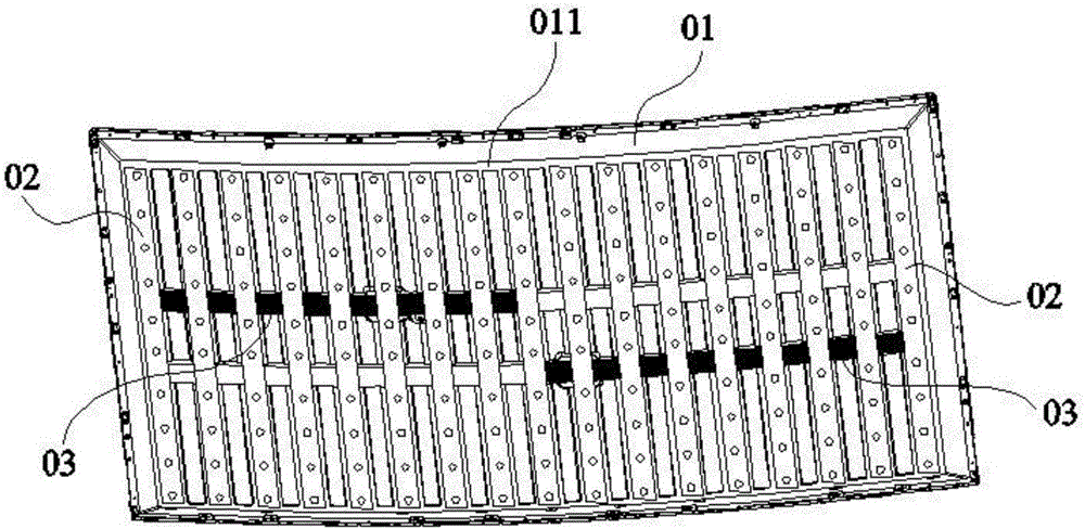
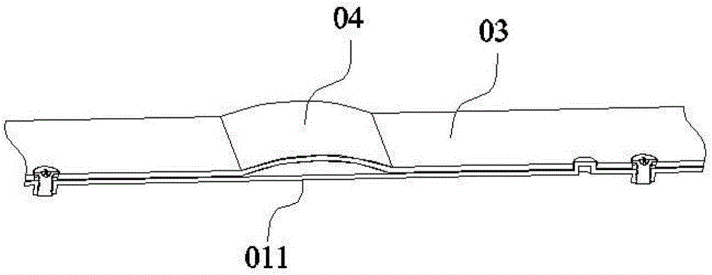
[0005] The partial swelling of the connecting piece 03 may affect the flatness of the reflective sheet, resulting in a decrease in the display effect of the curved display device; the partial swelling of the connecting piece 03 may also lift up part of the light bar 02 from the arc-shaped bottom plate 011, making the light Part of the LED lamps on the strip 02 is separated from the arc-shaped bottom plate 011 at the corresponding position on the surface of the light strip 02 facing the arc-shaped bottom plate 011. On the one hand, this part of the LED lights cannot be dissipated through the arc-shaped bottom plate 011. This in turn leads to poor heat dissipation of the LED lamp, burning out, and even igniting the reflector; on the other hand, the distance between this part of the LED lamp and other LED lamps and the display panel will be inconsistent, resulting in uneven display of the display panel; the partial swelling of the connector 03 may also cause The connector on it is displaced, resulting in a poor connection between the connector 03 and the light strip 02

Method used


Image

  • Backlight module and curved surface display device
  • Backlight module and curved surface display device
  • Backlight module and curved surface display device

Examples


Embodiment Construction

[0024] The technical solutions in the embodiments of the present invention will be clearly and completely described below in conjunction with the accompanying drawings in the embodiments of the present invention. Apparently, the described embodiments are only a partial embodiment of the present invention, rather than a complete embodiment. . Based on the embodiments of the present invention, all other embodiments obtained by persons of ordinary skill in the art without making creative efforts belong to the protection scope of the present invention.

[0025] In the description of the present invention, it should be noted that unless otherwise specified and limited, the terms "installation", "connection" and "connection" should be understood in a broad sense, for example, it can be a fixed connection or a detachable connection. Connected, or integrally connected; it may be mechanically connected or electrically connected; it may be directly connected or indirectly connected thro...


PUM

PropertyMeasurementUnit
Heightaaaaaaaaaa

Abstract

The invention discloses a backlight module and a curved surface display device and relates to the technical field of display, aiming at solving the problems that poor heat dissipation of an LED (Light Emitting Diode), overburning of the LED lamp and ignition of a reflection sheet are caused by the fact that a connecting piece partially protrudes towards on one side far away from an arc-shaped bottom plate, the display effect is reduced, and the connection between a lamp bar plate and the connecting piece is not good and the like. The backlight module comprises a back plate, wherein the back plate comprises the arc-shaped bottom plate; the arc-shaped bottom plate is provided with the lamp bar plate, a driving plate, and a long-strip-shaped connecting piece for electrically connecting the lamp bar plate with the driving plate; the long-strip-shaped connecting piece is arranged on one side of a concave surface of the arc-shaped bottom plate along a bending direction of the arc-shaped bottom plate; the lamp bar plate is vertical to the length direction of the connecting piece; a supporting part is arranged between the connecting piece and the arc-shaped bottom plate; one end of the supporting part is connected with the arc-shaped bottom plate and the other end of the supporting part is connected with the connecting piece; and a space for allowing the connecting piece to be deformed towards on one side close to the arc-shaped bottom plate is formed in at least one side of the supporting part. The backlight module is used for providing light for a display panel.

Description

technical field [0001] The invention relates to the field of display technology, in particular to a backlight module and a curved display device. Background technique [0002] In a curved liquid crystal display device, a backlight module is usually used to provide light for the liquid crystal panel. [0003] refer to figure 1 , the backlight module of the curved liquid crystal display device includes a metal backplane 01, and the arc-shaped bottom plate 011 of the metal backplane 01 is provided with a light bar board 02, a driving board (not shown in the figure) and a light bar board 02 for electrical connection. and the connecting piece 03 of the driving board, the driving board can control whether each LED lamp on the light bar board 02 is turned on. [0004] Such as figure 2 As shown, the connecting piece 03 is usually in close contact with the arc-shaped bottom plate 011, so that the connecting piece 03 is in a bent state meeting the requirement of curvature engageme...

Claims


Application Information

Patent Timeline
IPC IPC(8): G02F1/13357
CPCG02F1/133603G02F1/133606G02F1/133608G02F1/133607
Inventor 陈友才
Owner HISENSE VISUAL TECH CO LTD
Learn More