
A 3D imaging method for terahertz radar targets based on dual-frequency interference

A technology for three-dimensional imaging and radar targets, which is applied in the directions of radio wave reflection/re-radiation, utilization of re-radiation, measurement devices, etc. It can solve the problems of high complexity of imaging system and nonlinearity constraints of terahertz signal source signal in imaging performance, etc. , to achieve the effect of simple imaging process, avoiding the influence of signal nonlinearity, and avoiding measurement errors

Active Publication Date: 2018-01-19
NAT UNIV OF DEFENSE TECH
View PDF3 Cites 0 Cited by
  • Summary
  • Abstract
  • Description
  • Claims
  • Application Information

AI Technical Summary

Problems solved by technology

In the existing array-based U-V interference 3D imaging method in the terahertz frequency band, the large number of array elements will lead to high complexity of the imaging system; the imaging performance of the synthetic aperture imaging system based on broadband signals is severely restricted by the nonlinearity of the terahertz signal source signal

Method used


Image

  • A 3D imaging method for terahertz radar targets based on dual-frequency interference
  • A 3D imaging method for terahertz radar targets based on dual-frequency interference
  • A 3D imaging method for terahertz radar targets based on dual-frequency interference

Examples


Embodiment Construction

[0055] In order to make the purpose, technical solutions and beneficial effects of the present invention more clear, the present invention will be further described in detail below in conjunction with the accompanying drawings and embodiments. It should be noted that the specific embodiments described here are only used to explain the present invention, not to limit the present invention.

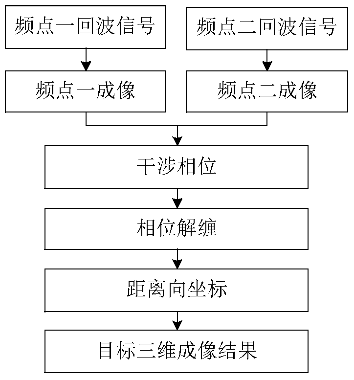
[0056] image 3 It is a flow chart of the present invention, which provides a three-dimensional imaging method for a terahertz radar target based on dual-frequency interference. Taking the rough cone as the target, the target model is as Figure 4 As shown, the radius of the base of the cone is 5cm, the height is 4.9cm, the roughness of the surface of the cone is 0.5mm, and the relative length is 0.5mm. From the enlarged picture of the top of the cone, it can be seen that the rough surface is divided into triangles. Utilizing the method of the present invention to carry out three-dimensio...


PUM


Abstract

The present invention provides a double-frequency interference-based THz radar target three-dimensional imaging method, wherein the coordinates of a target in three dimensions of distance, azimuth and pitch can be obtained. Meanwhile, the azimuth-pitch 2D image of the target, including the 2D coordinates of the target and the 2D scattering intensity distribution of the target, is obtained through the azimuth-pitch imaging process. The distance-dimension coordinates of the target are obtained through the interference treatment on two azimuth-pitch images of two adjacent frequency points. During the double-frequency interference-based azimuth-pitch imaging process, the small-angle two-dimensional rotation of a target is utilized to obtain the high resolution in the dimensions of both azimuth and pitch. Meanwhile, the double-frequency imaging mode avoids the usage of wideband signals during the 3D imaging process and the non-linear influence of signals. The above method is simple in imaging process and high in efficiency, which realizes the 3D imaging of a radar target.

Description

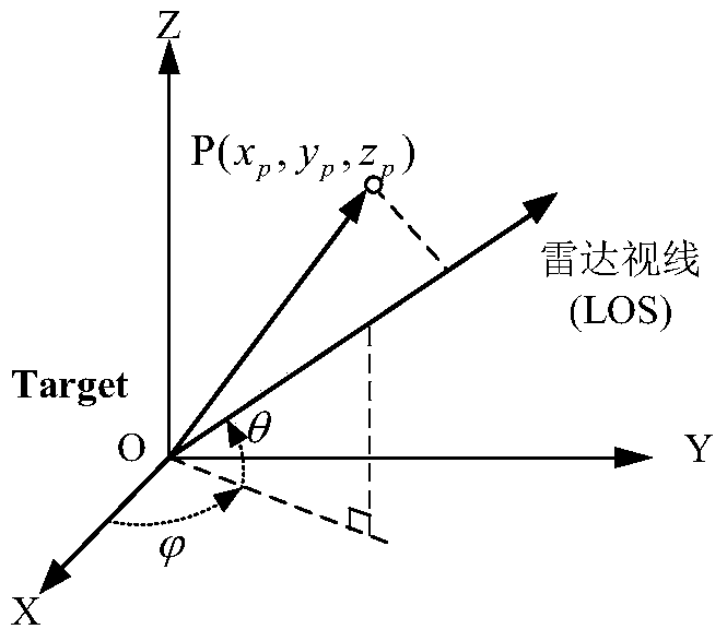
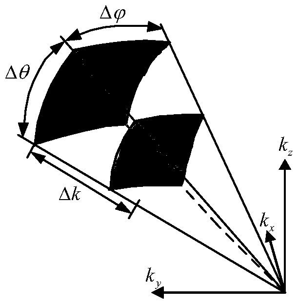
technical field [0001] The invention belongs to the technical field of radar imaging, in particular to an azimuth-elevation dual-frequency interference imaging method related to three-dimensional imaging of a terahertz radar target. Background technique [0002] For a given lateral resolution, the lateral aperture required for radar imaging is proportional to the wavelength. Compared with microwave radar, terahertz radar has a shorter wavelength, and the same imaging resolution can be obtained with a smaller lateral aperture. Therefore, high-resolution azimuth-elevation imaging can be achieved by using the small-angle two-dimensional rotation of the target in the terahertz frequency band; at the same time, since the roughness of the target surface can be compared with the wavelength in the terahertz frequency band, it can no longer be regarded as an ideal For a smooth surface, the number of scattering points increases sharply in the imaging result of the target, showing the ...

Claims


Application Information

Patent Timeline
Patent Type & Authority Patents(China)
IPC IPC(8): G01S13/89G01S7/41
CPCG01S7/41G01S13/89
Inventor 秦玉亮蒋彦雯王宏强邓彬高敬坤
Owner NAT UNIV OF DEFENSE TECH
Learn More