Partial deep-buried drainage ditch structure at tunnel base

A drainage ditch and partial technology, applied in the field of tunnel base drainage ditch structure, can solve problems such as increased construction risk, floating, and instability of tunnel arch wall, so as to reduce construction difficulty and risk and project cost, ensure operation safety, reduce The effect of water pressure

Active Publication Date: 2018-06-26
CHINA RAILWAY DESIGN GRP CO LTD
View PDF7 Cites 0 Cited by
  • Summary
  • Abstract
  • Description
  • Claims
  • Application Information

AI Technical Summary

Problems solved by technology

[0003] When the first method is used, the base water must enter the central ditch through the side wall drain holes, and the central ditch is located in the inverted arch filling, which has the problem of difficult drainage at the bottom of the tunnel. From the perspective of the tunnels that have been in operation, when the tunnel When the accumulated water at the bottom cannot be drained away smoothly, the lighter ones will infiltrate into the ballast bed along the weak position, and the base will turn mud and mud will flow out;
When using the second method, the water in the tunnel can basically be discharged smoothly, but on the one hand, the construction cost will remain high if the central deep-buried ditch or drainage tunnel is used for the entire length of the tunnel; on the other hand, combined with previous construction experience , in the center of the large-scale excavation at the bottom of the tunnel to deeply bury the ditch or drainage hole, the excavation of the construction will easily cause the invert arch of the initial support to be unable to be closed in time, and the excavation by means of blasting will also easily cause the instability of the tunnel arch wall. Greatly increase the construction risk, and there are many hidden dangers after the construction is completed

Method used


Image

  • Partial deep-buried drainage ditch structure at tunnel base
  • Partial deep-buried drainage ditch structure at tunnel base
  • Partial deep-buried drainage ditch structure at tunnel base

Examples


Embodiment Construction

[0026] The partial deep-buried drainage ditch structure at the tunnel base of the present invention will be further described below in conjunction with the accompanying drawings and specific embodiments. The following examples are only used to illustrate the present invention but not to limit the present invention.

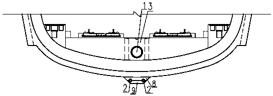
[0027] The partially deep-buried drainage ditch structure of the tunnel base of the present invention is suitable for local drainage of the tunnel base. The drainage structure adopts a deep-buried drainage ditch at the base of the tunnel, and an inspection well at the end and a catchment well. Enter the central ditch, and discharge out of the cave through the central ditch.

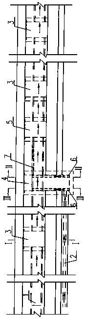
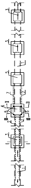
[0028] figure 1 It is a longitudinal sectional view of the tunnel base part deep buried drain structure of the present invention; figure 2 It is a top view of the partially deep-buried drainage ditch at the tunnel base of the present invention. Such as figure 1 and figure 2 As shown, ...


PUM


Abstract

The invention discloses a tunnel base local deep-buried drainage ditch structure. The tunnel base local deep-buried drainage ditch structure comprises a center drainage pipe located in tunnel inverted arch padding and a plurality of inspection wells arranged in the length direction of the center drainage pipe. A local deep-buried drainage ditch is arranged in a tunnel base, an end inspection well is arranged in one end of the local deep-buried drainage ditch, a water catchment well is arranged in the downstream of the end inspection well, the end inspection well and the water catchment well are communicated through a plurality of vertical water guide pipes and a plurality of longitudinal water guide pipes, and the water catchment well is communicated with the center drainage pipe. Accumulated water in the tunnel base is collected into the end inspection well through the local deep-buried ditch, then enters the water catchment well through the vertical water guide pipes and the longitudinal water guide pipes and finally is drained out of the tunnel through the center drainage pipe. The tunnel base local deep-buried drainage ditch structure is suitable for locally draining water in the tunnel base, the construction difficulty and risk caused when a center deep-buried ditch is arranged in the whole tunnel and the project cost are reduced, water pressure borne by a tunnel structure is reduced, lining structure water leakage and even lining cracking caused in the construction and operation period of the tunnel are prevented, and operation safety is guaranteed.

Description

technical field [0001] The invention relates to a tunnel base drainage ditch structure, in particular to a partially deeply buried drainage ditch structure arranged at the tunnel base. Background technique [0002] At present, there are two ways to drain the tunnel base: one is to let the accumulated water in the tunnel enter the side ditch through the side wall drain hole, and then introduce the side ditch into the central ditch located in the inverted arch filling. This method is more common; the other One is to set a central deep-buried ditch or a drainage tunnel at the bottom of the tunnel to directly drain the water out of the tunnel. This method is often used in the entrance section of the tunnel in cold or severe cold regions, and it is also used in other situations. Although these drainage systems can be successfully implemented in various strata and play a certain role, many problems have been found during construction and operation, mainly as follows: [0003] Whe...

Claims


Application Information

Patent Timeline
Patent Type & Authority Patents(China)
IPC IPC(8): E21F16/02
CPCE21F16/02
Inventor 马志富杨昌贤夏勇冯山群陈换利曲耀慧曾青王乐明李岩王洪昌俞尚宇李光京吴小策
Owner CHINA RAILWAY DESIGN GRP CO LTD
Why Eureka
Try Eureka