
Method for eliminating heat deviation of working medium of external heat exchanger

A heat exchanger, external technology, applied in the direction of combustion method, lighting and heating equipment, fuel burning in melting state, etc., can solve the difference of heat transfer effect, thermal deviation of working medium, material selection of external heat exchanger heating surface Difficulties and other problems to achieve the effect of improving the fluidization effect and eliminating the thermal deviation of the working fluid

Active Publication Date: 2016-06-08
DONGFANG BOILER GROUP OF DONGFANG ELECTRIC CORP
View PDF12 Cites 7 Cited by
  • Summary
  • Abstract
  • Description
  • Claims
  • Application Information

AI Technical Summary

Problems solved by technology

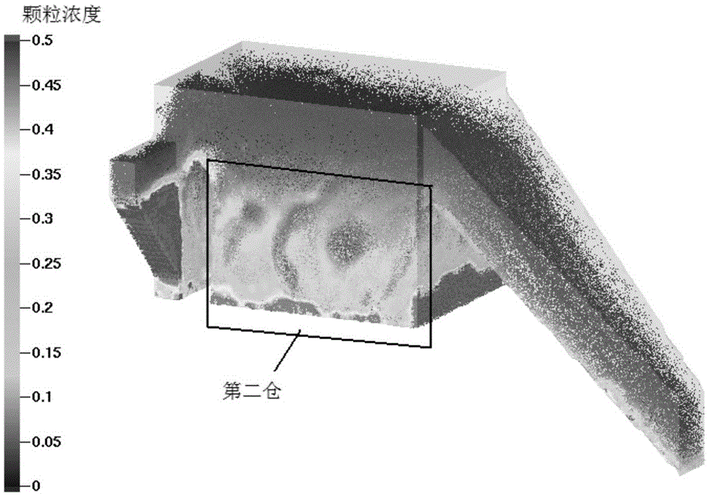
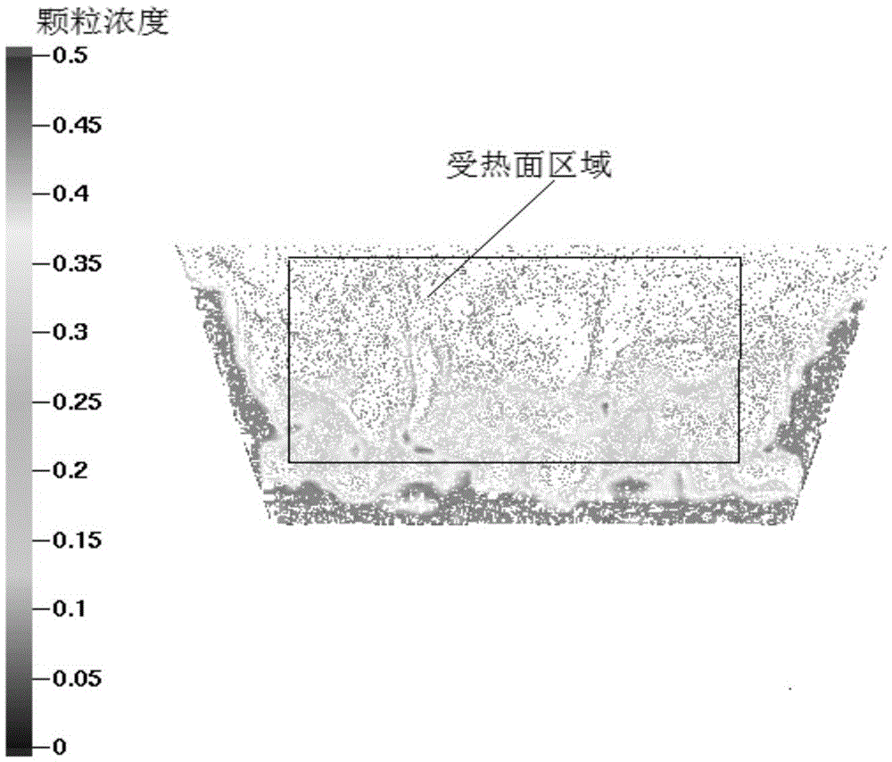
Depend on figure 1 It can be seen that the concentration of particles around the bottom of the second chamber of the external heat exchanger is much higher than that in the center area, indicating that the fluidization characteristics of the particles in the side wall area and the middle area are different; the heat transfer effect is different from that in the center area, which eventually leads to the existence of working fluid. thermal deviation
[0008] The thermal deviation of the working medium of the external heat exchanger is particularly prominent in the development process of circulating fluidized bed boilers with ultra-supercritical parameters and above, which makes it difficult to select materials for some heating surfaces in the external heat exchanger, which limits the efficiency of circulating fluidized bed boilers. The development towards higher parameters, larger capacity and higher efficiency makes it difficult to further improve the efficiency of circulating fluidized bed boiler units

Method used


Image

  • Method for eliminating heat deviation of working medium of external heat exchanger
  • Method for eliminating heat deviation of working medium of external heat exchanger
  • Method for eliminating heat deviation of working medium of external heat exchanger

Examples


Embodiment 1

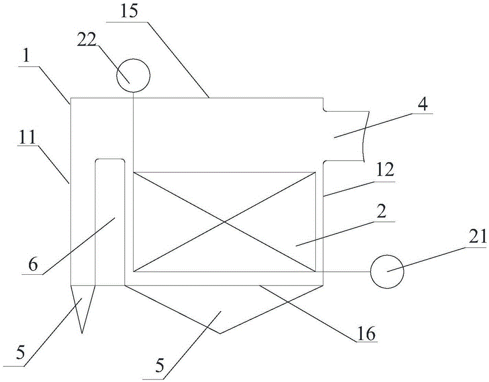
[0033] Such as image 3 , Figure 4 , Figure 5 As shown, an external heat exchanger for a 660MW ultra-supercritical circulating fluidized bed boiler includes a shell 1, a partition wall 6, a heating surface tube panel 2, an inlet header 21, an outlet header 22, an inlet ash Road 3, outlet gray road 4, air chamber 5, wind cap; shell 1 includes front wall 11 and rear wall 12, first side wall 13 and second side wall 14, top plate 15 and bottom air distribution plate along the particle flow direction 16. The width of the top plate is L1, and the width of the bottom air distribution plate 16 is L, wherein L is designed according to the specific standard of the heat exchanger; the inlet header 21 and the outlet ash channel 4 are located on the rear wall 12 of the shell 1 , the outlet header 22 is located on the top plate 15 of the housing 1, the inlet ash channel 3 is located on the second side wall 14 of the housing 1, and the air chamber 5 is located under the air distribution ...

Embodiment 2

[0037] Such as Figure 6 , Figure 7 As shown, an external heat exchanger for a circulating fluidized bed boiler with a parameter of 700°C, including a shell 1, a partition wall 6, a tube panel 2 on a heating surface, an inlet header 21, an outlet header 22, and an inlet gray passage 3. Exit ash channel 4, air chamber 5, air cap; shell 1 includes front wall 11 and rear wall 12, first side wall 13 and second side wall 14, top plate 15 and bottom air distribution plate 16 along the particle flow direction , the width of the top plate is L1, the width of the bottom air distribution plate 16 is L, the inlet header 21 and the outlet ash channel 4 are located on the rear wall 12 of the shell 1, and the outlet header 22 is located on the top plate of the shell 1 15, the inlet gray passage 3 is located on the second side wall 14 of the housing 1, and the air chamber 5 is located under the air distribution plate 16 on the bottom surface of the housing 1; Divided into three compartmen...

Embodiment 3

[0041] Such as Figure 8 As shown, the difference between this embodiment and the second embodiment is that the angle β between the two side walls and the extension surface of the bottom air distribution plate 16 is 45°, so that the heating surface can be arranged in a wider space, and the external type The ratio of the width B of the gray channel 4 at the outlet of the heat exchanger to the width L1 of the top plate 15 is 0.6, so that the width can fully cover the width of the tube panel on the heating surface of the external heat exchanger, thereby achieving the purpose of reducing the thermal deviation of the working medium.


PUM


Abstract

The invention relates to the technical field of external heat exchangers of circulating fluidized bedboilers and aims to provide a method for eliminating heat deviation of a working medium of an external heat exchanger. A first side wall and a second side wall of a shell of the external heat exchanger incline outwards. An included angle beta formed between the first side wall and the extending face of a bottom face wind distribution plate and an included angle beta formed between the second side wall and the extending face of the bottom face wind distribution plate range from 30 degrees to 90 degrees. Blast capacities entering a bin from a hood on the bin inner bottom face wind distribution plate where a heating surface pipe screen is located are sequentially distributed from outside to inside according to the sequence from large to small. Through the methods thata heating surface pipe is not arranged in a side shielding area of the external heat exchanger, or the working medium does not circulate in the heating surface pipe in the side shielding area and the like, so that the heat deviation is eliminated. The technical scheme is combined with actual operation data of the external heat exchanger, by means of theoretical analysis and numerical calculation, the fluidization effect of the side shielding area is effectively improved, or the poor fluidization area is avoided, the heat deviation of the working medium of the external heat exchanger is eliminated, and the foundation is laid for developing the circulating fluidized bedboilers with efficient ultra-supercritical parameters or above.

Description

technical field [0001] The invention belongs to the technical field of fluidized bed power generation, in particular to the technical field of external heat exchangers for large circulating fluidized bed boilers. Background technique [0002] Circulating fluidized bed combustion technology is a new type of clean coal combustion technology, and its main feature is that the fuel burns in a fluidized state in the furnace. Circulating fluidized bed combustion technology has been widely used in the world due to its advantages in energy saving and environmental protection. As of the end of 2015, a total of 9 supercritical circulating fluidized bed boilers have been put into operation in the world, and circulating fluidized bed combustion technology has fully entered the supercritical era. However, in order to pursue higher power generation efficiency and the national plan for energy conservation and emission reduction, the requirements for coal consumption of existing and new coa...

Claims


Application Information

Patent Timeline
Patent Type & Authority Applications(China)
IPC IPC(8): F23C10/28
CPCF23C10/28
Inventor 徐鹏胡修奎霍锁善鲁佳易巩李明薛大勇张定海苏虎聂立周棋
Owner DONGFANG BOILER GROUP OF DONGFANG ELECTRIC CORP
Learn More