Maintenance device with optimized control system for hydroelectric power station
A maintenance device and optimized control technology, which is applied to fluid-driven starting devices, engine control, engine components, etc., can solve the problems of complex engine structure, insufficient output torque, and inaccurate control, so as to ensure speed and reduce pulsation. , the effect of economical and practical structure
- Summary
- Abstract
- Description
- Claims
- Application Information
AI Technical Summary
Problems solved by technology
Method used
Image

Examples
Embodiment 1
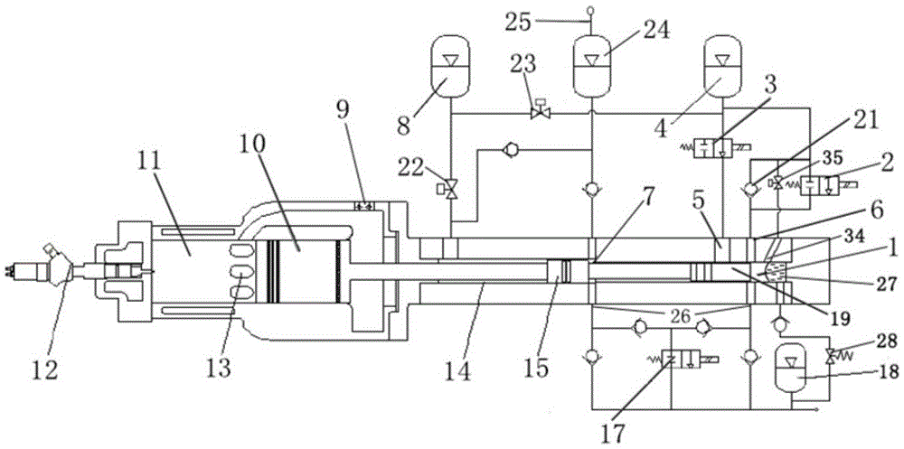
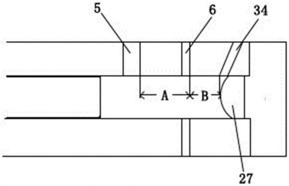
[0019] Embodiment 1: as Figure 1-3A maintenance device for a hydropower station with an optimized control system is shown, including a maintenance vehicle and an engine connected to the maintenance vehicle. The engine is used to drive the maintenance vehicle. The engine includes a power part, an oil injection system and a hydraulic part. The power Part includes intake check valve 9, power piston 10, combustion chamber 11, fuel injector 12, scavenging port 13, return piston 15, compression piston 19, hydraulic part includes compression chamber 1, pump chamber 7, return chamber 14 And a hydraulic circuit, the compression chamber 1 is arranged at the rear of the engine, on which a first oil port 5 and a second oil port 6 are arranged, and the first oil port 5 and the second oil port 6 pass through the first oil port respectively The control valve 3 and the second control valve 2 are connected with the compression accumulator 4, and the pump chamber 7 is respectively connected wi...
Embodiment 2
[0030] Embodiment 2: as Figure 1-3 A maintenance device for a hydropower station with an optimized control system is shown, including a maintenance vehicle and an engine connected to the maintenance vehicle. The engine is used to drive the maintenance vehicle. The engine includes a power part, an oil injection system and a hydraulic part. The power Part includes intake check valve 9, power piston 10, combustion chamber 11, fuel injector 12, scavenging port 13, return piston 15, compression piston 19, hydraulic part includes compression chamber 1, pump chamber 7, return chamber 14 And a hydraulic circuit, the compression chamber 1 is arranged at the rear of the engine, on which a first oil port 5 and a second oil port 6 are arranged, and the first oil port 5 and the second oil port 6 pass through the first oil port respectively The control valve 3 and the second control valve 2 are connected with the compression accumulator 4, and the pump chamber 7 is respectively connected w...
Embodiment 3
[0041] Embodiment 3: as Figure 1-3 A maintenance device for a hydropower station with an optimized control system is shown, including a maintenance vehicle and an engine connected to the maintenance vehicle. The engine is used to drive the maintenance vehicle. The engine includes a power part, an oil injection system and a hydraulic part. The power Part includes intake check valve 9, power piston 10, combustion chamber 11, fuel injector 12, scavenging port 13, return piston 15, compression piston 19, hydraulic part includes compression chamber 1, pump chamber 7, return chamber 14 And a hydraulic circuit, the compression chamber 1 is arranged at the rear of the engine, on which a first oil port 5 and a second oil port 6 are arranged, and the first oil port 5 and the second oil port 6 pass through the first oil port respectively The control valve 3 and the second control valve 2 are connected with the compression accumulator 4, and the pump chamber 7 is respectively connected w...
PUM
 Abstract
Description
Claims
Application Information
 - Generate Ideas
- Intellectual Property
- Life Sciences
- Materials
- Tech Scout
- Unparalleled Data Quality
- Higher Quality Content
- 60% Fewer Hallucinations
Browse by: Latest US Patents, China's latest patents, Technical Efficacy Thesaurus, Application Domain, Technology Topic, Popular Technical Reports.
© 2025 PatSnap. All rights reserved.Legal|Privacy policy|Modern Slavery Act Transparency Statement|Sitemap|About US| Contact US: help@patsnap.com