
Energy-saving road sweeping vehicle

A road sweeping and cleaning technology, which is applied to road cleaning, cleaning methods, construction, etc., can solve the problems of increased machine manufacturing costs, low friction between the broom and the ground, and poor cleaning effect, achieving low cost, good cleaning effect, and reduced The effect of manufacturing costs

Active Publication Date: 2016-06-08
SANMEN MUNICIPAL ENG CO LTD
View PDF6 Cites 9 Cited by
  • Summary
  • Abstract
  • Description
  • Claims
  • Application Information

AI Technical Summary

Problems solved by technology

[0002] At present, most of the urban roads have realized the cleaning operation of suction-sweeping sweepers, but most of the cleaning work of rural roads is neglected, mainly because the cost of traditional sweeping vehicles is too high, and the sides of rural roads are generally relatively low-lying. Most of the pollutants are leaves, dust and small stones, which have less pollution to the soil, so the above pollutants can be cleaned to the low-lying areas on the roadside. The existing pure-sweeping cleaning vehicles for rural roads are not ideal, as announced in application number 201410787046.2 "A Simple Cleaning Device", which uses a fixed shaft to support the turntable and a motor to drive the cleaning device to rotate. The angle between the rotation axis of the support turntable and the road surface is fixed, and the broom is brought into contact with the road surface by relying on the natural hem of the connecting arm. In this way, the broom has no spring tension, the friction between the broom and the ground is small, and the broom cannot be effectively protected when encountering obstacles. The broom has a small turning radius and poor cleaning effect. manufacturing cost of the machine

Method used


Image

  • Energy-saving road sweeping vehicle
  • Energy-saving road sweeping vehicle
  • Energy-saving road sweeping vehicle

Examples


Embodiment 1

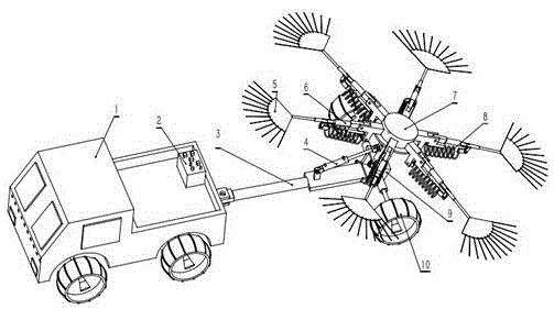
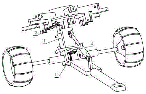
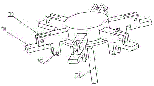
[0013] Embodiment 1: An energy-saving road sweeper, including a tractor 1, a hydraulic system 2, a drawbar 3, a first hydraulic cylinder 4, a cleaning brush 5, a swing arm 6, a central turntable 7, a tension spring 8, and a rear axle 9. Wheel 10, second hydraulic cylinder 11, universal wheel 12, driving helical gear 13, driven helical gear 14. The hydraulic system 2 is arranged at the rear of the tractor 1 and is connected to the oil inlet and outlet ports at both ends of the first hydraulic cylinder 4 and the second hydraulic cylinder 11 through pipelines, and the power of the hydraulic system 2 is provided by the engine of the tractor 1 . One end of the drawbar 3 is hinged at the rear of the tractor 1, the other end is hinged at the bottom of the rear axle 9, and a first hydraulic cylinder 4 is arranged between the drawbar 3 and the rear axle 9; the first hydraulic cylinder 4 The rear part of the cylinder block is hinged on the rear and upper part of the drawbar 3, and the ...


PUM


Abstract

The invention provides an energy-saving road sweeping vehicle which comprises a tractor, a hydraulic system, a traction rod, a first hydraulic cylinder, a cleaning brush, a swinging arm and the like, wherein the hydraulic system is arranged at the rear part of the tractor, and is respectively connected with oil inlet and outlet openings in the two ends of cylinder bodies of the first hydraulic cylinder and a second hydraulic cylinder through pipelines; the power of the hydraulic system is provided by an engine of the tractor; one end of the traction rod is hinged to the rear part of the tractor, and the other end of the traction rod is hinged to the lower part of a rear axle; the first hydraulic cylinder is arranged between the traction rod and the rear axle. A rotation axis of a central turntable and an angle of a pavement can be adjusted at any moment according to pavement conditions and different wastes, so that the cleaning brush is always in an optimal working state. The energy-saving road sweeping vehicle provided by the invention is simple in structure, low in cost and good in sweeping effect.

Description

technical field [0001] The invention relates to the field of road sanitation cleaning equipment, in particular to an energy-saving road sweeper. Background technique [0002] At present, most of the urban roads have realized the cleaning operation of suction-sweeping sweepers, but most of the cleaning work of rural roads is neglected, mainly because the cost of traditional sweeping vehicles is too high, and the sides of rural roads are generally relatively low-lying. Most of the pollutants are leaves, dust and small stones, which have less pollution to the soil, so the above pollutants can be cleaned to the low-lying areas on the roadside. The existing pure-sweeping cleaning vehicles for rural roads are not ideal, as announced in application number 201410787046.2 "A Simple Cleaning Device", which uses a fixed shaft to support the turntable and a motor to drive the cleaning device to rotate. The angle between the rotation axis of the support turntable and the road surface is ...

Claims


Application Information

Patent Timeline
Patent Type & Authority Applications(China)
IPC IPC(8): E01H1/05
CPCE01H1/05
Inventor 不公告发明人
Owner SANMEN MUNICIPAL ENG CO LTD
Learn More