Distributing valve and gasket

A distribution valve and valve column technology, applied in the direction of fluid distribution valve, distribution device, multi-way valve, etc., can solve the problems of increased user burden, expensive distribution valve, large space for distribution valve installation, etc., and achieves good sealing effect.

Active Publication Date: 2016-06-01
KOGANEI
View PDF7 Cites 0 Cited by
  • Summary
  • Abstract
  • Description
  • Claims
  • Application Information

AI Technical Summary

Problems solved by technology

Therefore, when it is required to supply lubricant to, for example, more than eight movable parts, it is impossible to use one distribution valve.
In such a situation, multiple distribution valves are used, but the addition of distribution valves requires additional auxiliary parts, piping, etc.
[0007] Also, since the dispensing valve with the integrally formed valve main body is an expensive product, the fact that a plurality of dispensing valves are used not only increases the burden on the user, but also requires a large space in terms of dispensing valve installation.

Method used


Image

  • Distributing valve and gasket
  • Distributing valve and gasket
  • Distributing valve and gasket

Examples


Embodiment Construction

[0037] A plurality of embodiments related to the distribution valve of the present invention will be sequentially described with reference to the drawings.

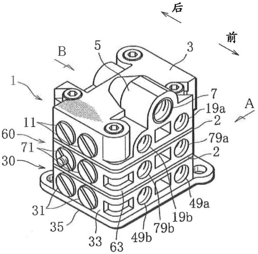
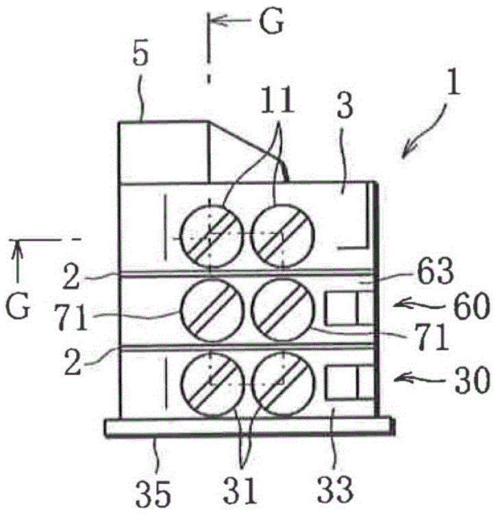
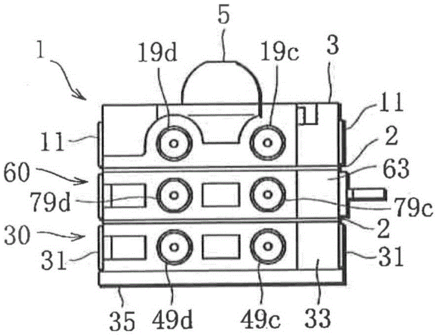
[0038] figure 1 A perspective view of the distribution valve according to the first embodiment is shown, and the distribution valve is used to distribute fluid. The fluid here may have viscosity, and examples of such a viscous fluid include lubricants such as grease. figure 2 as well as image 3 Respectively show the side and back of the above distribution valve, Figure 4 The main features of the distribution valve according to the present invention are clearly shown.

[0039] From Figure 1 ~ Figure 3 It can be seen that the distribution valve of the first embodiment includes: a top block (first block) 1, a bottom block (second block) 30, and a single intermediate block (third block) 60 arranged between the blocks 1 and 30. . Among the above-mentioned blocks 1, 30, 60, the top block 1 is arranged at the top, and on the oth...


PUM


Abstract

This distributing valve has: a top block (1) provided with an injection opening (7); a base block (30); and at least one intermediate block (60) sandwiched between the top block (1) and the base block (30). Each block incorporates a pair of valve spools (15, 45, 75), but meanwhile has a plurality of discharge openings (19, 49, 79). When the top block (1), base block (30), and intermediate block (60) are superposed, a complex pathway is formed within the blocks from the injection opening (7) to each discharge opening (19, 49, 79), and while the complex pathway causes the sequential reciprocating motion of each valve spool by means of a lubricant injected from the injection opening (7), meanwhile the lubricant is sequentially discharged from each discharge opening (19, 49, 79) using the reciprocating motion of each valve spool.

Description

Technical field [0001] The present invention relates to a distribution valve that sequentially discharges injected fluid from a plurality of discharge ports, and a gasket suitable for the distribution valve. Background technique [0002] Large vehicles such as trucks and buses, construction machinery, and industrial machinery include multiple movable parts such as bearings, and these movable parts require the supply of lubricant. For the supply of such a lubricant, a distribution valve having a plurality of discharge ports is used, and the lubricant is sequentially discharged from the discharge ports. [0003] Therefore, it is desired that such a distribution valve can distribute lubricant to as many movable parts as possible. [0004] For example, Patent Literature 1 discloses such a distribution valve. The distribution valve of Patent Literature 1 includes a valve body integrally molded by aluminum die-casting, an injection port, a plurality of valve columns (valvespool), and each...

Claims


Application Information

Patent Timeline
Patent Type & Authority Applications(China)
IPC IPC(8): F16N25/02F16J15/12F16K11/22F16K21/00F16K27/00F16K27/04
CPCF16K11/22F16K27/003F16K27/041F15B13/0839
Inventor 浅井秀次
Owner KOGANEI
Why Eureka
Try Eureka