A tunable optical filter based on lithium niobate and its application
An optical filter, lithium niobate technology, applied in instruments, optics, nonlinear optics, etc., can solve the problems of unfavorable devices such as polarization insensitivity, expand the tunable ability, overcome the polarization insensitivity characteristics, which are not conducive to realization, zero sensitivity, etc. The effect of power consumption
- Summary
- Abstract
- Description
- Claims
- Application Information
AI Technical Summary
Problems solved by technology
Method used
Image

Examples
Embodiment 1
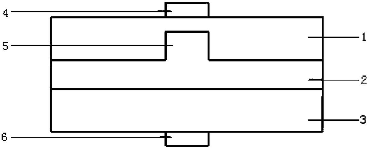
[0040] like Figure 1-3 shown.
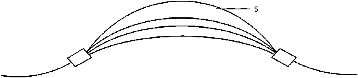
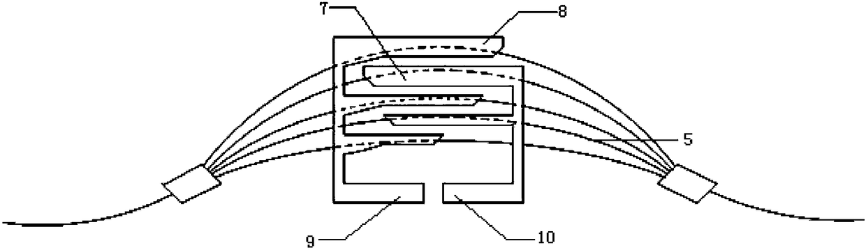
[0041] A tunable optical filter based on lithium niobate, comprising an upper confinement layer 1, a lithium niobate waveguide layer 2 and a lower confinement layer 3 stacked in sequence from top to bottom; the upper surface of the upper confinement layer 1 is provided with an upper electrode 4. The lower surface of the lower confinement layer 3 is provided with a lower electrode 6; the lithium niobate waveguide layer 2 is a lithium niobate thin film provided with an arrayed waveguide grating on the upper surface; the upper electrode 4 includes even-numbered waveguide electrodes inserted into each other 10 and odd-numbered waveguide electrodes 9; the even-numbered waveguide electrodes 10 are provided with two even-numbered slots 7; the odd-numbered waveguide electrodes 9 are provided with three odd-numbered slots 8, and the even-numbered slots 7 and odd-numbered slots 8 are arranged alternately; the even-numbered slots The lengths of 7 and odd...
Embodiment 2
[0045] The difference of the tunable optical filter based on lithium niobate as described in Embodiment 1 is that the upper confinement layer and the lower confinement layer are respectively an upper confinement layer of silicon dioxide and a lower confinement layer of silicon dioxide.
Embodiment 3
[0047] A method for tuning using the lithium niobate-based tunable optical filter described in embodiment 1-2, comprising the following steps:
[0048] 1) Center wavelength tuning mode:
[0049] Simultaneously load the in-phase voltage with the same voltage value on the odd-numbered waveguide electrodes 9 and the even-numbered waveguide electrodes 10, so that the phase difference of the light wave in the adjacent waveguide changes, and then changes the position where the diffraction maximum value of each wavelength in the output waveguide appears; in this working mode Odd-numbered waveguide electrodes 9 and even-numbered waveguide electrodes 10 can be regarded as indifferent electrodes;
[0050] Applying voltage to the electrode will change the refractive index, that is, change the optical path difference. From the output result, the central wavelength of the filter output will change; the position where the diffraction maximum appears is equivalent to the central wavelength o...
PUM
 Abstract
Description
Claims
Application Information
 - R&D
- Intellectual Property
- Life Sciences
- Materials
- Tech Scout
- Unparalleled Data Quality
- Higher Quality Content
- 60% Fewer Hallucinations
Browse by: Latest US Patents, China's latest patents, Technical Efficacy Thesaurus, Application Domain, Technology Topic, Popular Technical Reports.
© 2025 PatSnap. All rights reserved.Legal|Privacy policy|Modern Slavery Act Transparency Statement|Sitemap|About US| Contact US: help@patsnap.com