
Heat pump drying system adopting industrial circulating water as heat source

An industrial circulating water, heat pump drying technology, applied in heat recovery systems, dryers for static materials, heat pumps, etc., can solve the problems of insufficient and efficient recovery of low-grade heat sources, waste of energy utilization, etc., to improve energy utilization, reduce Effects of Environmental Pollution

Active Publication Date: 2016-06-01
QUANZHOU INST OF EQUIP MFG
View PDF10 Cites 2 Cited by
  • Summary
  • Abstract
  • Description
  • Claims
  • Application Information

AI Technical Summary

Problems solved by technology

[0006] The above-mentioned heat pump drying system cannot fully and efficiently recover the heat from low-taste heat sources, and there is still waste in energy utilization.

Method used


Image

  • Heat pump drying system adopting industrial circulating water as heat source
  • Heat pump drying system adopting industrial circulating water as heat source

Examples


Embodiment Construction

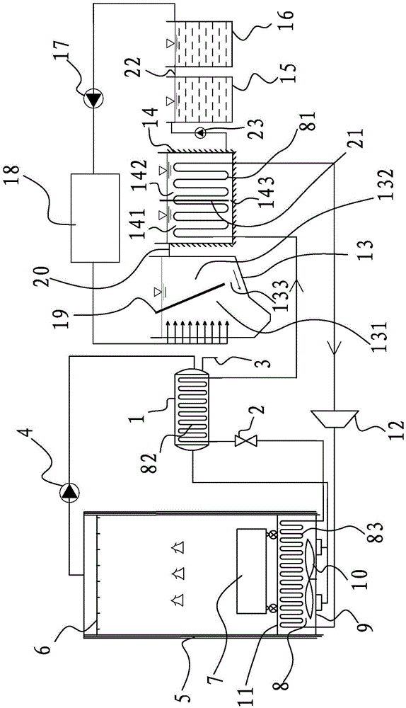
[0040] In order to make the object, technical solution and advantages of the present invention clearer, the present invention will be further described in detail below in conjunction with the accompanying drawings and embodiments. The specific embodiments described here are only used to explain the present invention, not to limit the present invention. It should be noted that the arrow symbol "→" in the drawings of the description refers to the flow direction of the medium in the pipeline, and the appearance of the arrow symbol does not limit the protection scope of the present invention.

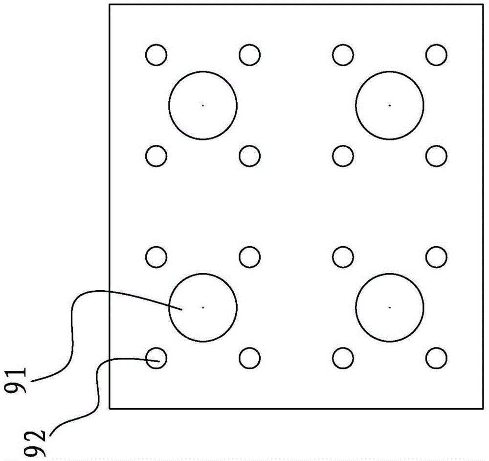
[0041] refer to figure 1 and figure 2, a heat pump drying system using industrial circulating water as a heat source, including a drying box 5, a condenser 8, a compressor 12, an evaporator 1, a throttle 2, and a fan 10, and the throttle 2 is a throttle valve. The air leakage support plate 11 is provided in the box 5, the drying box 5 is provided with an air inlet 9 and an air outlet, an...


PUM


Abstract

The invention relates to a heat pump drying system adopting industrial circulating water as a heat source. The heat pump drying system comprises a drying case, a condenser, a compressor, an evaporator, a throttle and a fan, wherein the drying case is provided with an air inlet and an air outlet. The system further comprises a primary settling pond, a heat recovery pond and a settling pond, wherein a first heat conducting portion is arranged in the heat recovery pond, a second heat conducting portion is arranged in the evaporator, and the condenser is provided with a third heat conducting portion corresponding to the air inlet. The inlet end of the compressor communicates with the outlet end of the first heat conducting portion, and the outlet end of the compressor communicates with the inlet end of the third heat conducting portion. The inlet end of the throttle communicates with the outlet end of the third heat conducting portion, and the outlet end of the throttle communicates with the inlet end of the second heat conducting portion. The outlet end of the second heat conducting portion communicates with the inlet end of the first heat conducting portion. The inlet end of the evaporator communicates with the air outlet, and the outlet end of the evaporator communicates with the air inlet. The heat pump drying system can reduce energy consumption, improve the energy utilization rate and reduce environment pollution.

Description

technical field [0001] The invention relates to a heat pump drying system using industrial circulating water as a heat source. Background technique [0002] In my country, the energy used in drying operations accounts for about 14-35% of industrial energy consumption, and a large number of low-grade heat sources such as industrial wastewater above 5°C are wasted and cannot be rationally utilized. Industrial waste heat belongs to renewable energy, and its rational use can improve energy utilization and reduce power consumption, bringing good social and environmental benefits. [0003] Industrial wastewater is a waste heat energy. The production process of stone mainly includes two processes of cutting and polishing. In order to improve the service life of the tool, production efficiency and product quality, etc., it is necessary to use water to cool the tool and remove grinding debris during the processing process, forming sewage that absorbs a large amount of heat. Howeve...

Claims


Application Information

Patent Timeline
Patent Type & Authority Applications(China)
IPC IPC(8): F26B9/06F26B21/00F25B30/06C02F1/00
CPCC02F2001/007F25B30/06F26B9/06F26B21/002Y02B30/52Y02P70/10
Inventor 石一磊陈龙祥谢媚娜王森林
Owner QUANZHOU INST OF EQUIP MFG
Learn More