Detector control system

A control system and detector technology, applied in the electrical field, can solve problems such as unusability, and achieve the effect of overcoming the small measurement range

Inactive Publication Date: 2016-06-01
赵俭
View PDF0 Cites 0 Cited by
  • Summary
  • Abstract
  • Description
  • Claims
  • Application Information

AI Technical Summary

Problems solved by technology

According to experience at home and abroad, sonar detection technology is generally used. The traditional method is to use the cable to drag the sonar to move vertically up and down in the salt rock karst cavity to detect the shape of the cavity. This method is easy to implement for vertical karst cavities, but for diameter It cannot be used in horizontal salt rock caverns with a length of tens of meters or even hundreds of meters and a length of hundreds of meters.

Method used


Image

  • Detector control system

Examples


Embodiment Construction

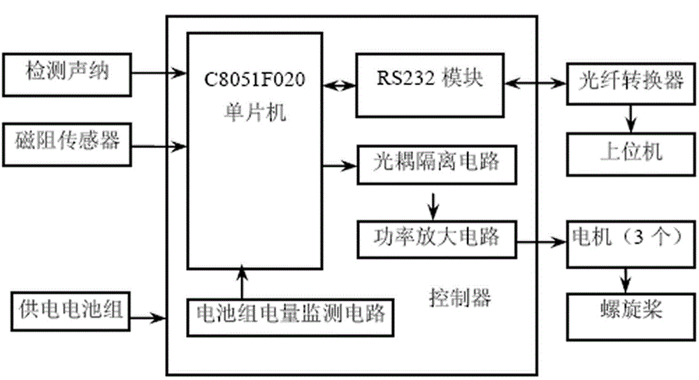
[0010] As shown in the figure, the present invention includes a controller, a detection sonar module, a magnetoresistive sensor, a power supply battery pack, an optical fiber converter, a host computer, a motor and a propeller; it is characterized in that: the controller includes a single-chip RS232 module, an optocoupler Isolation circuit battery pack power monitoring circuit, power amplifier circuit, comparison module, storage module, wireless receiving module; the input port of the controller's microcontroller is connected to the monitoring sonar module and the magnetoresistive sensor, and the power supply battery pack is connected to the controller's battery pack power monitoring circuit ; The RS232 module of the controller is connected to the optical fiber converter, and the optical fiber converter is connected to the comparison module, the storage module, the wireless receiving module and the host computer; the power amplifier circuit is connected to the optocoupler isolat...


PUM


Abstract

The invention belongs to the technical field of electrics and particularly relates to a detector control system. The detector control system provided by the invention is convenient to use and operate in various environment states. The detector control system comprises a controller, a detection sonar module, a magnetoresistive sensor, a power supply battery pack, an optical fiber converter, an upper computer, motors and propellers. The detector control system is characterized in that the controller comprises a single chip microcomputer, an RS232 module, an optically-coupled isolation circuit, a battery pack electricity quantity monitoring circuit, a power amplification circuit, a comparison module, a storage module and a wireless receiving module; an input port of the single chip microcomputer of the controller is connected with the detection sonar module and the magnetoresistive sensor, and the power supply battery pack is connected with the battery pack electricity quantity monitoring circuit of the controller; the RS232 module of the controller is connected with the optical fiber converter, and the optical fiber converter is connected with the comparison module, the wireless receiving module and the upper computer; and the power amplification circuit is connected with the optically-coupled isolation circuit and the motors, and the output ends of the motors are connected with the propellers.

Description

technical field [0001] The invention belongs to the technical field of electricity, and in particular relates to a detector control system. Background technique [0002] With the rapid development of the national economy and the growing demand for energy, the underground salt karst cavity is considered an ideal place for oil and gas storage and waste disposal due to its low permeability, good sealing, and high safety and stability. In order to rationally utilize the storage space of the salt karst cavern and ensure its multiple benefits such as economy, high efficiency, and environmental protection, it is necessary to first measure the structure, shape and size of the cavern. According to domestic and foreign experience, sonar detection technology is generally used. The traditional method is to use the cable to drag the sonar to move vertically up and down in the salt karst cavity to detect the shape of the cavity. This method is easy to implement for vertical cavities, but ...

Claims


Application Information

Patent Timeline
IPC IPC(8): E21B49/00
Inventor 赵俭
Owner 赵俭
Why Eureka
Try Eureka