Pneumatic conveying device and auxiliary pipeline control system of pneumatic conveying device

A technology of conveying pipelines and auxiliary pipelines, which is applied to conveying bulk materials, conveyors, transportation and packaging, etc., can solve the problems of inaccurate adjustment of conveying air volume, low utilization rate of fluidizing nozzles and pressurizing nozzles, etc.

Active Publication Date: 2016-06-01
BEIJING GUODIAN FUTONG SCI & TECH DEV
View PDF7 Cites 7 Cited by
  • Summary
  • Abstract
  • Description
  • Claims
  • Application Information

AI Technical Summary

Problems solved by technology

[0006] Therefore, the technical problem to be solved by the present invention is to overcome the defect of inaccurate air volume adjustment in existing pneumatic conveying pipelines, thereby providing a pneumatic conveying device with precise air volume adjustment
[0007] Another technical problem to be solved by the present invention is to overcome the defects of low utilization rate of fluidization nozzles and pressurization nozzles in the prior art, thereby providing a pneumatic conveying device with high utilization rate of fluidization nozzles and pressurization nozzles and Auxiliary Pipeline Control System for Pneumatic Conveying Devices

Method used


Image

  • Pneumatic conveying device and auxiliary pipeline control system of pneumatic conveying device
  • Pneumatic conveying device and auxiliary pipeline control system of pneumatic conveying device

Examples


Embodiment 1

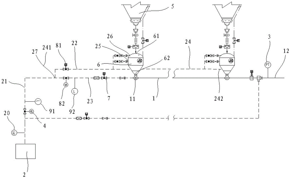
[0088] Such as figure 1 Shown, a kind of pneumatic conveying device of the present invention comprises:

[0089] A conveying pipeline 1, at least one material drop port 11 is provided on the side wall of the conveying pipeline 1;

[0090] The air intake device 2 communicates with the conveying pipeline 1, injects compressed air into the conveying pipeline 1, and transports the materials falling into the conveying pipeline 1;

[0091] Also includes:

[0092] The material path pressure detection device 3 is arranged between the material falling inlet 11 downstream of the conveying pipeline 1 close to the inlet device 2 and the discharge end 12 of the conveying pipeline 1, and detects that the conveying pipeline 1 The material path pressure;

[0093] The main flow adjustment device 4 is used to adjust the gas flow rate of the air intake device 2 to the delivery pipeline 1;

[0094] The intelligent control system is used to control the adjustment of the main flow regulating devi...

Embodiment 2

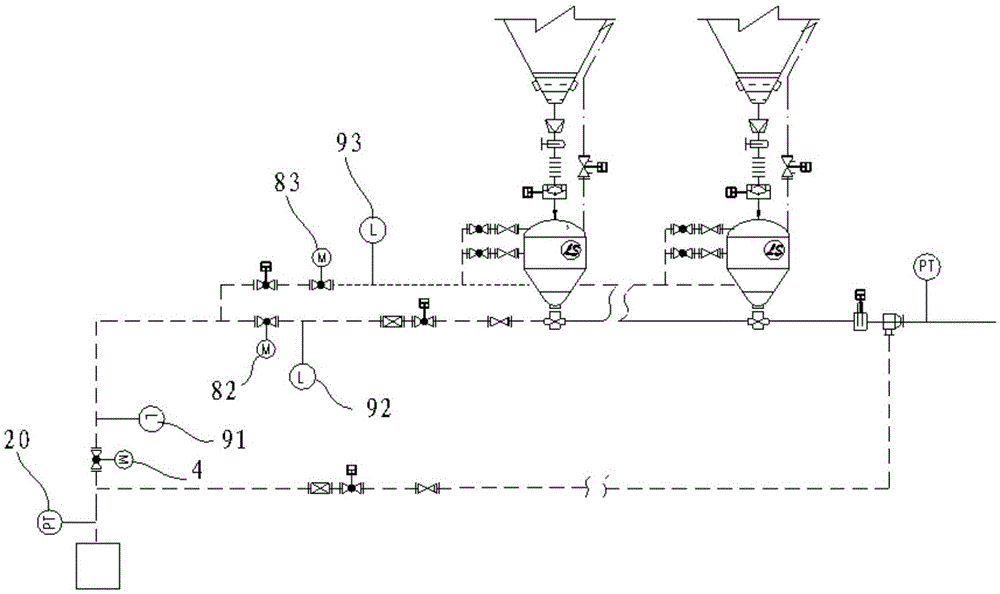
[0143] Such as figure 2 As shown, this embodiment is substantially the same as Embodiment 1, except that the specific form and arrangement of the flow regulating device and the flow detecting device are different.

[0144] In this embodiment, the flow regulating device includes an auxiliary pipeline flow regulating device 83, which is arranged on the auxiliary pipeline 24 and is located between the branch 27 and the first delivery tank 6 close to the branch 27. time, used to adjust the real-time gas flow of the auxiliary pipeline 24;

[0145] The flow detection device includes an auxiliary pipeline flow detection device 93, which is arranged on the auxiliary pipeline 24 and between the auxiliary pipeline flow adjustment device 83 and the first delivery tank 6 near the branch 27 , detecting the real-time gas flow rate of the auxiliary pipeline 24 and feeding it back to the controller.

[0146] As a modified embodiment, the flow regulating device further includes a conveying ...


PUM


Abstract

The invention discloses a pneumatic conveying device which comprises a conveying pipeline, an air feeding device, a material way pressure detecting device, a main flow adjusting device and an intelligent control system, wherein the conveying pipeline is provided with a material falling inlet, the air feeding device is used for introducing compressed air into the conveying pipeline so that materials can fall into the conveying pipeline, the material way pressure detecting device is arranged on the portion, close to the downstream portion of a material falling inlet of the air feeding device, of the conveying pipeline, and the intelligent control system is used for controlling adjustment of the main flow adjusting device according to the material way pressure detected by the material way pressure detecting device. An auxiliary pipeline control system of the pneumatic conveying device comprises a flow detecting device, a flow adjusting device and a controller, wherein the flow detecting device is used for detecting real-time air flow of the auxiliary pipeline, the flow adjusting device is used for adjusting the air flow of the auxiliary pipeline, and the controller comprises a receiving unit, a comparing unit and a processing unit. By the adoption of the pneumatic conveying device and the auxiliary pipeline control system of the pneumatic conveying device, the pressure of a material way mixed with the materials can be directly detected, measuring results and flow adjustment are more accurate, and the utilization rate of a fluidization nozzle and a pressurization nozzle is increased.

Description

technical field [0001] The invention relates to the field of material transportation, in particular to a pneumatic conveying device and an auxiliary pipeline control system for the pneumatic conveying device. Background technique [0002] At present, in the construction of hydropower or thermal power projects, there are generally two ways to transport powder materials such as lime powder, yellow sand, fly ash, etc. to the construction site. The other is through the pneumatic conveying device, which adopts the principle of gas-solid two-phase flow, uses compressed air as the medium and power of conveying materials, and conveys the powdery and granular materials from the transfer silo to the conveying pipeline through the conveying pipeline. On the construction site, this method has low investment and fast transportation, and has been widely used in the industry. [0003] During the conveying process of the pneumatic conveying device, if the pressure in the conveying pipeline...

Claims


Application Information

Patent Timeline
Patent Type & Authority Applications(China)
IPC IPC(8): B65G53/66B65G53/52B65G53/58
CPCB65G53/52B65G53/58B65G53/66
Inventor 张玉王峰杜岩李新生薄俊杰范力遥董启强马飞育李子甲李明明
Owner BEIJING GUODIAN FUTONG SCI & TECH DEV
Why Eureka
Try Eureka