
Automatic feeding multi-head melt extrusion forming 3d printing equipment

A melt extrusion, 3D printing technology, applied in metal processing equipment, 3D object support structures, manufacturing tools, etc., can solve problems such as low work efficiency and slow printing speed, save production costs, increase stability, reduce effect of distance

Active Publication Date: 2018-07-31
ANHUI SCI & TECH UNIV
View PDF3 Cites 0 Cited by
  • Summary
  • Abstract
  • Description
  • Claims
  • Application Information

AI Technical Summary

Problems solved by technology

[0003] The purpose of the present invention is to provide an automatic feeding multi-head melt extrusion forming 3D printing equipment, which solves the technical defects of slow printing speed and low work efficiency of 3D printers in the prior art

Method used


Image

  • Automatic feeding multi-head melt extrusion forming 3d printing equipment
  • Automatic feeding multi-head melt extrusion forming 3d printing equipment
  • Automatic feeding multi-head melt extrusion forming 3d printing equipment

Examples


Embodiment 1

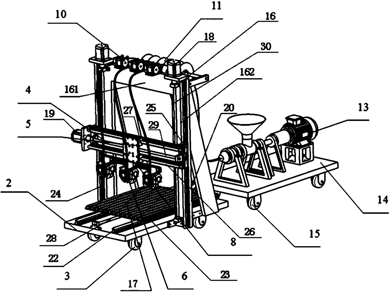
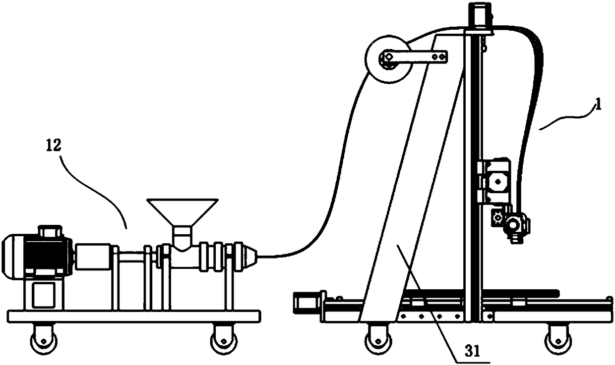
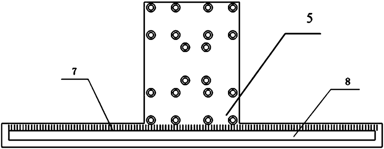
[0029] Such as Figure 1 to Figure 4 The automatic feeding multi-head melt-extrusion 3D printing equipment shown includes a 3D printer 1 and an injection molding machine 12; the 3D printer 1 includes a 3D printer base 2, a 3D printer bracket 16 fixed on both sides of the 3D printer base 2, The X-axis module 4 which is arranged on the 3D printer support 16 and forms a vertical movement pair with the 3D printer support 16, and the print head mounting plate 5 which is arranged on the X-axis module 4 and the X-axis module 4 constitutes a horizontal movement pair. The 3D printer base 2 and the 3D printer base 2 form a horizontally movable printing object support platform 17, the print head mounting plate 5 and the printing object support platform 17 move in a vertical direction, the print head mounting plate 5 is in an inverted T shape, and the print head The vertical part of the mounting plate 5 is slidably mounted on the X-axis module 4, and several print heads 6 are detachably mo...

Embodiment 2

[0040] Compared with the first embodiment, the difference between this embodiment and the first embodiment is that the number of the first motors 18 is two, which are respectively fixed on the top of the two vertical supports 162, and the output shafts of the two first motors 18 are each provided with a first motor. The screw 30 and the two first screw rods 30 are respectively screwed to the two ends of the X-axis module 4, and the rotation direction and pitch of the two first screw rods 30 are the same, and the two first motors 18 rotate synchronously. The rest of the structure is the same as the first embodiment.

Embodiment 3

[0042] The difference between this embodiment and the first embodiment is that the 3D printer 1 and the injection molding machine 12 have a separate structure. The bottom of the 3D printer base 2 is provided with a printer universal wheel 3, and the bottom of the injection molding machine 12 is provided with an injection molding machine universal wheel 15. The rest of the structure of this embodiment is the same as the first embodiment.


PUM


Abstract

The invention discloses an automatic feeding multi-head melt extrusion forming 3D printing equipment, including a 3D printer and an injection molding machine; the 3D printer includes a 3D printer base, a 3D printer support, an X-axis module that forms a vertical movement pair with the 3D printer support, The print head mounting plate that forms a horizontal movement pair with the X-axis module, and the printing object support platform that forms a horizontal movement pair with the 3D printer base, the print head mounting plate is perpendicular to the direction of movement of the printing object support platform, and the print head mounting plate is inverted T In the shape of a font, the vertical part of the print head mounting plate is slidably installed on the X-axis module, and more than one print head is detachably installed on the horizontal part. The beneficial effects of the present invention are: setting up multi-printing heads that can be easily disassembled, increasing or decreasing, and adjusting spacing to print at the same time; Utilization and equipment utilization, saving production costs.

Description

Technical field [0001] The invention relates to an automatic feeding multi-head melt extrusion forming 3D printing equipment. Background technique [0002] 3D printing equipment has slow printing speed, low work efficiency, and high material costs, which cannot be adapted to rapid production and mass production. However, the existing solution is to extend the printing working time and use inferior materials instead, which will delay the product development cycle, fail to quickly occupy the market, and lose a large amount of market share. Inferior products will also damage the brand image and are very unsuitable for rapid product upgrades. Development requirements. Summary of the invention [0003] The purpose of the present invention is to provide an automatic feeding multi-head melt extrusion forming 3D printing device, which solves the technical defects of slow printing speed and low working efficiency of 3D printers in the prior art. [0004] In order to solve the above problem...

Claims


Application Information

Patent Timeline
Patent Type & Authority Patents(China)
IPC IPC(8): B29C64/118B29C64/336B33Y30/00B33Y40/00
Inventor 陈丰洪腾蛟曾其良孟凡盛丁凤娟
Owner ANHUI SCI & TECH UNIV
Learn More