A co2 laser marking machine

A technology of laser marking machine and laser marking head, which is applied in the field of CO2 laser marking machines, can solve the problems of unsatisfactory users, poor marking quality, and low marking efficiency, so as to avoid pollution of equipment and the surrounding environment, and protect Safety and health, high marking efficiency

Active Publication Date: 2018-08-24
广州佳帆计算机有限公司
View PDF6 Cites 0 Cited by
  • Summary
  • Abstract
  • Description
  • Claims
  • Application Information

AI Technical Summary

Problems solved by technology

Existing CO 2 Laser marking machines generally only have one laser marking head, which can only mark one workpiece at a time, and since the marking heads are relatively fixed, when it is necessary to perform inclined images, characters, numbers on the workpiece Or when the line is marked, the angle cannot be adjusted accurately, which cannot meet the needs of users. In addition, the existing marking machine cannot fix the workpiece. If the workpiece deviates during the marking process, the marking quality will appear. The problems of poor marking efficiency and low marking efficiency, the existing CO 2 There are still technical defects in the laser marking machine, which cannot meet various marking needs

Method used


Image

  • A co2 laser marking machine
  • A co2 laser marking machine
  • A co2 laser marking machine

Examples


Embodiment Construction

[0021] The present invention will be further described below in conjunction with embodiment:

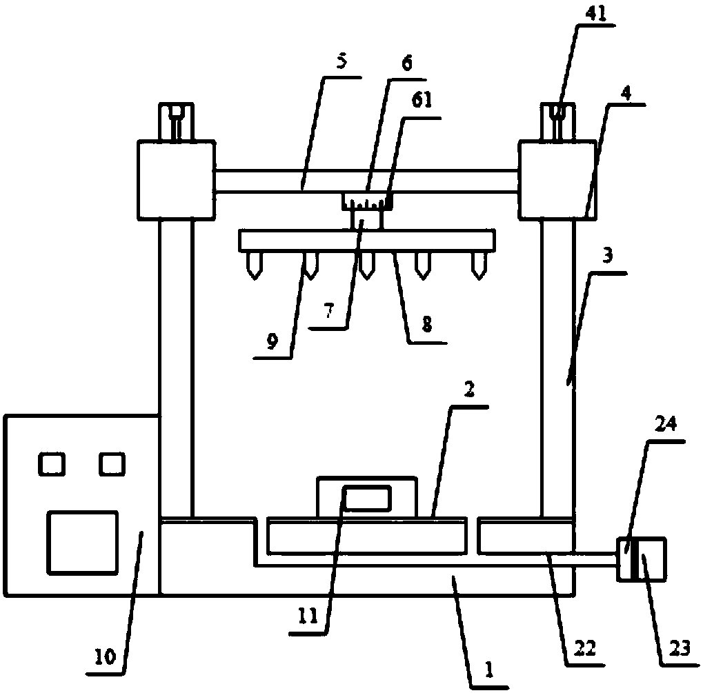
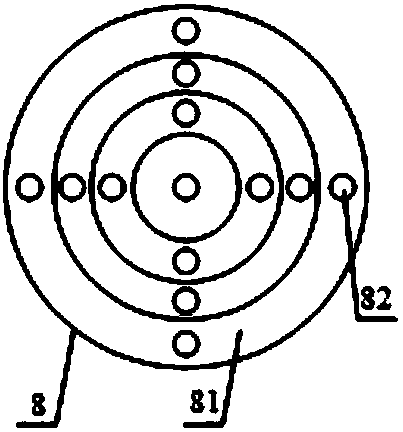
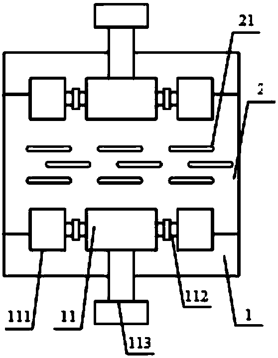
[0022] Such as Figure 1-3 As shown, the present invention provides a CO 2 A laser marking machine includes a base 1, a workbench 2, a sliding column 3, a slider 4, a fixed plate 5, a bearing seat 6, a rotating shaft 7, a marking head mounting plate 8, a laser marking head 9 and a controller 10, all The base 1 is provided with a workbench 2, and four sliding columns 3 are symmetrically arranged on both sides of the base 1, and a slider 4 is set on the sliding column 3, and the slider 4 is fixedly connected with the fixed plate 5, The bottom end of the fixed plate 5 is provided with a bearing seat 6, and the marking head mounting plate 8 is connected with the bearing seat 6 through a rotating shaft 7, and the bottom end of the marking head mounting plate 8 is provided with several laser marking heads 9, One side of the base 1 is provided with a controller 10;

[0023] The slider 4 ...


PUM


Abstract

The invention relates to a CO2 laser marking machine which comprises a base, a working platform, sliding columns, sliding blocks, a fixing plate, a bearing support, a rotating shaft, a marking head mounting disc, laser marking heads and a controller, wherein the marking head mounting disc is provided with a plurality of annular mounting ways sharing the same circle center; a plurality of mounting holes are formed in the annular mounting ways; the laser marking heads are mounted in the mounting holes; workpiece fixing blocks are symmetrically arranged at the front and rear sides of the working platform, and are connected with push hydraulic cylinders; and the two ends of the workpiece fixing blocks are connected with auxiliary fixing blocks through extension connecting rods. The CO2 laser marking machine is provided with the multiple laser marking heads, can carry out transverse, longitudinal and oblique marking on workpieces, can fix the workpieces of different sizes, is high in marking efficiency and good in marking quality, and can meet various different marking requirements.

Description

technical field [0001] The invention relates to the technical field of laser equipment, in particular to a CO 2 laser marking machine. Background technique [0002] Laser marking machine (laser marking machine) is to use laser beams to make permanent marks on the surface of various materials. The effect of marking is to expose the deep material through the evaporation of the surface material, so as to carve exquisite patterns, trademarks and characters. Laser marking machines are mainly divided into: CO 2 Laser marking machine, semiconductor laser marking machine, fiber laser marking machine and YAG laser marking machine, currently laser marking machines are mainly used in some occasions that require finer and higher precision. CO 2 Laser marking machine is CO 2 laser with CO 2 gas as the medium, the CO 2 Fill the discharge tube with other auxiliary gases and apply high voltage on the electrode, a glow discharge is generated in the discharge tube, and the gas releases ...

Claims


Application Information

Patent Timeline
Patent Type & Authority Patents(China)
IPC IPC(8): B23K26/362B23K26/14B23K26/08B23K26/142B23K26/70B23K37/04
CPCB23K26/0869B23K26/14B23K26/142B23K26/361B23K26/702B23K26/703B23K26/706B23K37/0443
Inventor 刘明辉江勇朱秀梅
Owner 广州佳帆计算机有限公司
Why Eureka
Try Eureka