Bus bar rolling structure

A converging belt and calendering technology, which is applied in the direction of metal rolling, metal rolling, and metal rolling racks, can solve the problems of low torque transmission efficiency, large fluctuations in the thickness of finished products, and defective products, so as to improve torque transmission Efficiency, the effect of improving the processing quality

Inactive Publication Date: 2016-06-01
SHENZHEN KEPSUN PRECISION TECH CO LTD
View PDF5 Cites 2 Cited by
  • Summary
  • Abstract
  • Description
  • Claims
  • Application Information

AI Technical Summary

Problems solved by technology

In practice, it has been found that the rolling structure with this design will cause the force direction of the upper calender wheel and the lower calender wheel to be uncoordinated due to the relative sliding misalignment between the support and the mechanism frame, which directly leads to the thickness of the rolled product. Large size fluctuations lead to defective products
In addition, the common rolling structure uses the upper calender wheel and the lower calender wheel as the power transmission mechanism respectively through the synchronous pulley, gear and coupling, which not only further leads to inconsistent rotation speeds of the upper calender wheel and the lower calender wheel, but also leads to The deviation of the torque on the motor relative to the output torque of the motor is large, that is, the torque transmission efficiency is low

Method used


Image

  • Bus bar rolling structure
  • Bus bar rolling structure
  • Bus bar rolling structure

Examples


Embodiment Construction

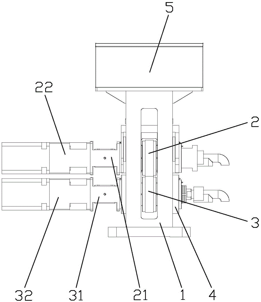
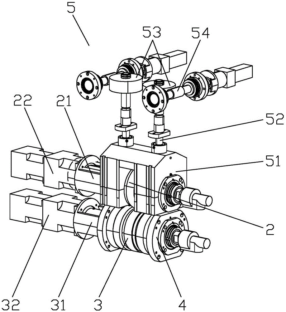
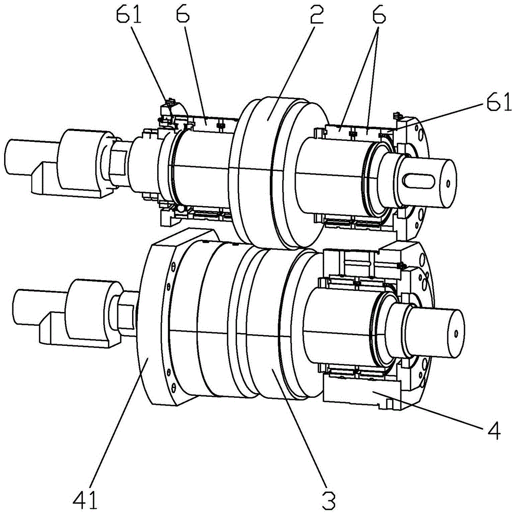
[0016] In order to make the purpose, technical solution and advantages of the present application clearer, the present invention will be further described in detail below in conjunction with the accompanying drawings and embodiments. In the ensuing description some specific details are referred to for a thorough understanding of the present invention. While the present invention may still be practiced without these specific details, the descriptions and representations herein are used by those skilled in the art to effectively convey the substance of their work to others skilled in the art. In addition, it should be noted that the words "front", "rear", "left", "right", "upper" and "lower" used in the following description refer to the direction in the drawings or the relative direction of the structure, The words "inside" and "outside" respectively refer to directions toward or away from the geometric center of a specific component, and those skilled in the art who make simpl...


PUM


Abstract

The invention discloses a bus bar rolling structure. The bus bar rolling structure comprises a support; the support is connected with an upper rolling wheel module and a lower rolling wheel module; a fixing block connected with the support sleeves the lower rolling wheel module; the upper rolling wheel module is provided with a lifting module. According to the characteristics of bus bar rolling work, the rolling structure has the advantages of reducing rolling errors caused by changes of gaps between rolling rings of upper and lower rolling wheels and improving the processing quality by reasonable structural improvements and especially by lifting motion of the overall upper rolling wheel module, relative fixation of the lower rolling wheel module and a design that the upper rolling wheel module is controlled to move up and down by the lifting module.

Description

technical field [0001] The invention relates to the field of metal processing, in particular to a rolling structure applied to the processing of busbars. Background technique [0002] The bus strip is a kind of welding strip, generally used as a bare conductive part, installed on an insulator, collecting current from the power supply, and then distributing the current to the output feeder, used to connect the previous battery slices connected in series, usually used in the photovoltaic industry. Generally, the confluence belt is processed from bare copper. Specifically, the upper calendering wheel and the lower calendering wheel of the calendering structure are compressed to the copper material together, and the round copper material is rolled and formed, that is, the upper calendering wheel and the lower calendering wheel are respectively lifted and rolled. The action of the screw applies pressure to the copper. In practice, it has been found that the rolling structure wi...

Claims


Application Information

Patent Timeline
Patent Type & Authority Applications(China)
IPC IPC(8): B21B13/02B21B31/24
CPCB21B13/02B21B31/24B21B2013/021
Inventor 张东宇
Owner SHENZHEN KEPSUN PRECISION TECH CO LTD
Why Eureka
Try Eureka