
Porous artificial temporal-mandibular joint structure and making method

A temporomandibular joint and artificial technology, applied in the field of artificial bones, can solve problems such as single joint shape, difficult size design to meet patients, and combination, and achieve good biocompatibility

Inactive Publication Date: 2016-06-01
广东健齿生物科技有限公司
View PDF6 Cites 3 Cited by
  • Summary
  • Abstract
  • Description
  • Claims
  • Application Information

AI Technical Summary

Problems solved by technology

[0002] In the prior art, artificial temporomandibular joints generally use finished artificial joints, which have a single joint shape, which is a flat titanium plate with screw holes and a semicircular imitation condyle structure at the upper end.
This structure does not conform to the anatomical shape of the natural condyle, and the functional movement of the condyle sliding and rotation cannot be realized; in addition, most condyle prostheses are mass-produced finished products, and the size design is difficult to meet the needs of each patient
[0003] Even though the artificial temporomandibular joint prepared by metal 3D printing technology can meet the individual structural needs of the patient, its overall density is still quite different from that of the patient's original bone, making it difficult to combine with human tissue and prone to stress concentration

Method used

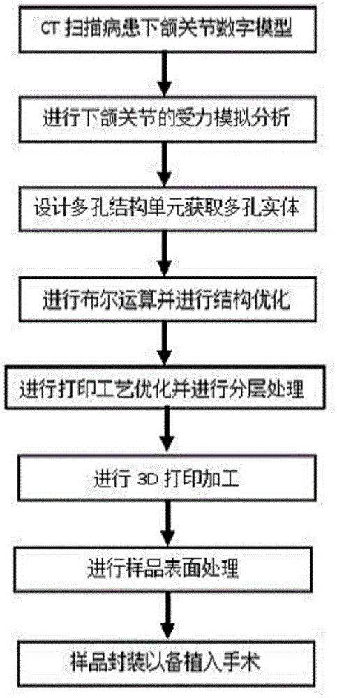
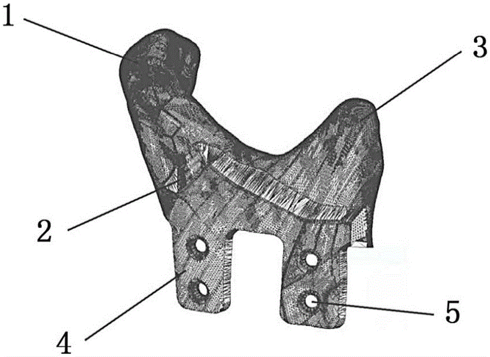
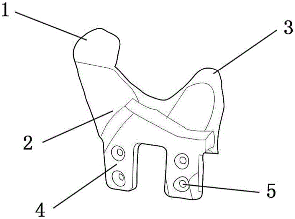

Image

  • Porous artificial temporal-mandibular joint structure and making method
  • Porous artificial temporal-mandibular joint structure and making method
  • Porous artificial temporal-mandibular joint structure and making method

Examples


Embodiment Construction

[0037] The idea, specific structure and technical effects of the present invention will be clearly and completely described below in conjunction with the embodiments and accompanying drawings, so as to fully understand the purpose, features and effects of the present invention. Apparently, the described embodiments are only some of the embodiments of the present invention, rather than all of them. Based on the embodiments of the present invention, other embodiments obtained by those skilled in the art without creative efforts belong to The protection scope of the present invention. In addition, all the connection / connection relationships mentioned in this article do not refer to the direct connection of components, but mean that a better connection structure can be formed by adding or reducing connection accessories according to specific implementation conditions. The various technical features in the invention can be combined interactively on the premise of not conflicting wi...


PUM

PropertyMeasurementUnit
Thicknessaaaaaaaaaa
Apertureaaaaaaaaaa
Thicknessaaaaaaaaaa

Abstract

The invention discloses a porous artificial temporal-mandibular joint structure and a making method.The porous artificial temporal-mandibular joint structure comprises a coracoid, a condyle process, a condyle process neck and titanium plates provided with nail holes.The coracoid protrudes from the front edge of the upper end of the condyle process neck, the condyle process protrudes from the back edge of the upper end of the condyle process neck, and the titanium plates are arranged at the lower end of the condyle process neck.The artificial temporal-mandibular joint is a porous component and is composed of a plurality of mesh units, the mesh units are in hollowed truncated octahedron shapes, the thickness of frames of the mesh units ranges from 200 microns to 300 microns, the apertures of the mesh units range from 500 microns to 1,250 microns, and the porosity of a porous body is 75%-80%.The strength of the porous artificial temporal-mandibular joint structure is similar to that of primary skeleton of a patient, the tenacity of the porous artificial temporal-mandibular joint structure is similar to that of the primary skeleton of the patient, stress concentration generated after implantation can be avoided, and the porous structure can assist peripheral tissues in combination with the artificial temporal-mandibular joint.

Description

technical field [0001] The invention relates to the technical field of artificial bones, in particular to a porous artificial temporomandibular joint structure and a manufacturing method. Background technique [0002] In the prior art, artificial temporomandibular joints generally use finished artificial joints, which have a single joint shape, which is a flat titanium plate with screw holes and a semicircular imitation condyle structure at the upper end. This structure does not conform to the anatomical shape of the natural condyle, and cannot realize the functional movement of the condyle sliding and rotation; in addition, most condylar prostheses are mass-produced finished products, and the size design is difficult to meet the needs of each patient. [0003] Even though the artificial temporomandibular joint prepared by metal 3D printing technology can meet the patient's individual structural needs, its overall density is still quite different from the patient's original ...

Claims


Application Information

Patent Timeline
IPC IPC(8): A61F2/30A61L27/06A61L27/56
CPCA61F2/3099A61F2002/30011A61F2002/3028A61F2002/30593A61F2002/30943A61F2002/30985A61F2310/00023A61L27/06A61L27/56A61L2430/24
Inventor 张春雨陈贤帅颜瑜王亚玲
Owner 广东健齿生物科技有限公司
Learn More