Electronic device with pifa type antenna and wireless signal transmitting/receiving device thereof
A technology for wireless signal transmission and electronic equipment, which is applied to antenna equipment with additional functions, antenna grounding devices, antenna supports/installation devices, etc., and can solve problems such as difficulty in ensuring radiation efficiency and radiation performance.
Active Publication Date: 2016-05-25
SAMSUNG ELECTRONICS CO LTD
View PDF4 Cites 2 Cited by
- Summary
- Abstract
- Description
- Claims
- Application Information
AI Technical Summary
Problems solved by technology
Electronic devices generally use PIFA-type antennas
The PIFA type antenna has a problem in that it is
Method used
View moreImage
Smart ImageViewing Examples
Examples
 PUM
 Abstract
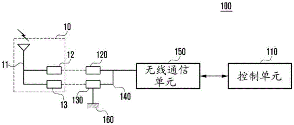
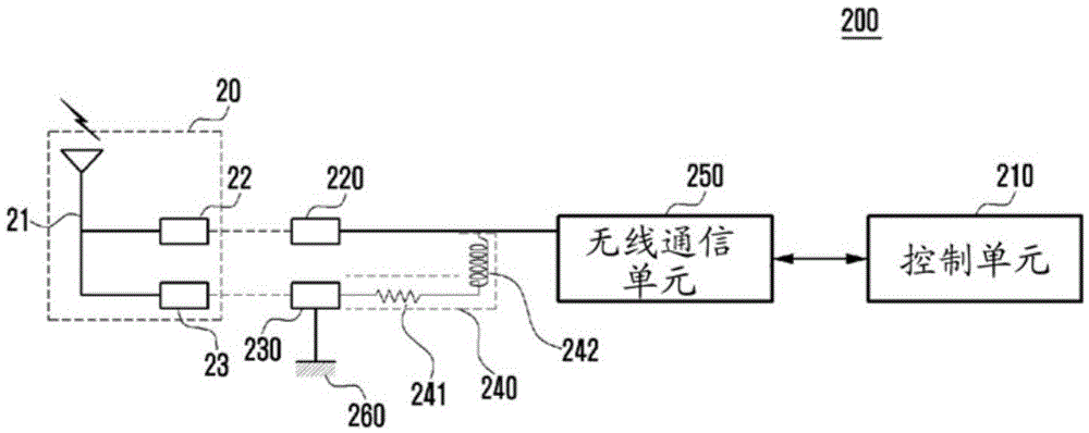
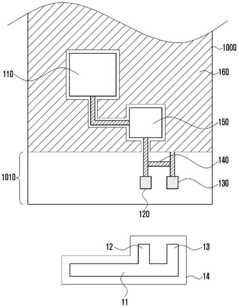
Various exemplary embodiments of the present disclosure relate to an electronic device with a Planar Inverted-F Antenna (PIFA) type antenna and a wireless signal transmitting/receiving device of the electronic device. The electronic device may include: a PIFA (Planar Inverted-F Antenna) type antenna which is transmitting or receiving a wireless signal; a wireless communication unit which is processing the transmitted or received wireless signal; a printed circuit board which is mounted with the wireless communication unit and includes a ground area; a power feeding pad which is electrically connected with a signal transmitting/receiving terminal of the wireless communication unit, and connected with a power feeding section of the PIFA type antenna when the PIFA type antenna is equipped in the electronic device; a ground pad which is electrically connected with the ground area, and connected with a ground section of the PIFA type antenna when the PIFA type antenna is equipped in the electronic device; and a connection section which forms an electric route between the power feeding pad and the ground pad. Meanwhile, various exemplary embodiments may be made based on a technical idea of the present disclosure.
Description
technical field [0001] Various exemplary embodiments of the present disclosure relate to an electronic device having a Planar Inverse F Antenna (PIFA) type antenna and a wireless signal transmitting / receiving device thereof. Background technique [0002] Recently, remarkable developments in information communication technology, semiconductor technology, and the like have rapidly increased the distribution and use of electronic devices. Furthermore, recent electronic equipment is a convergence of various types of terminals, rather than exclusively for one type of use. For example, mobile communication terminals provide various functions such as functions for watching TV (e.g., mobile broadcasting such as Digital Multimedia Broadcasting (DMB) or digital Video broadcasting (DVB)), music reproduction function (for example, MPEG Audio Layer-3 (MP3)), still image or moving image shooting function, Internet connection function, and radio reception function. Contents of the inven...
Claims
Login to View More Application Information
Patent Timeline
 IPC IPC(8): H01Q1/46H01Q1/48H01Q1/24
CPCH01Q1/243H01Q9/42H01Q9/0421H01Q1/12H04B1/44
Inventor 徐英勋
Owner SAMSUNG ELECTRONICS CO LTD
Features
- R&D
- Intellectual Property
- Life Sciences
- Materials
- Tech Scout
- Unparalleled Data Quality
- Higher Quality Content
- 60% Fewer Hallucinations
Learn More Browse by: Latest US Patents, China's latest patents, Technical Efficacy Thesaurus, Application Domain, Technology Topic, Popular Technical Reports.
© 2025 PatSnap. All rights reserved.Legal|Privacy policy|Modern Slavery Act Transparency Statement|Sitemap|About US| Contact US: help@patsnap.com


