Method for continuous laser processing using multi-position control, and system employing same

A laser processing method and laser processing technology, applied in the direction of manufacturing tools, laser welding equipment, metal processing equipment, etc., can solve problems such as reduced productivity and poor processing, and achieve the effects of high productivity, excellent processing quality, and fast processing

Active Publication Date: 2016-05-25
TECHNICS
View PDF5 Cites 2 Cited by
  • Summary
  • Abstract
  • Description
  • Claims
  • Application Information

AI Technical Summary

Problems solved by technology

At this time, if the moving speed cannot be correctly judged, and the speed of the high-speed driver is set for the path that the low-speed driver cannot travel, processing defects will occur. In order to prevent this, in many cases, only the Simple move speed is set to the maximum speed of the low-speed drive, reducing productivity
Also, movement needs to be done for all paths, so can cause unwanted movement or vibration etc.

Method used


Image

  • Method for continuous laser processing using multi-position control, and system employing same
  • Method for continuous laser processing using multi-position control, and system employing same
  • Method for continuous laser processing using multi-position control, and system employing same

Examples


Embodiment Construction

[0045] Hereinafter, preferred embodiments of the laser processing method according to the present invention will be described in detail with reference to the accompanying drawings.

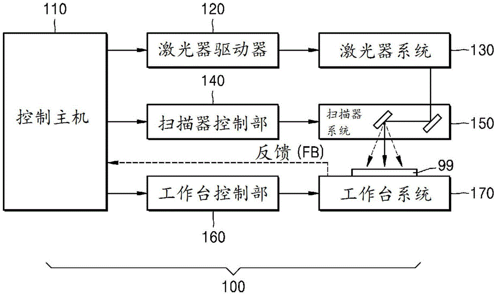
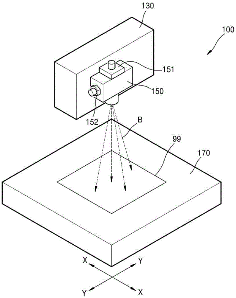
[0046] refer to figure 1 , laser processing system (LaserMachiningSystem) 100 is also called laser marking machine (marker) usually, comprises: workbench system (hereinafter referred to as workbench) 170, load workpiece 99 in described workbench system; Laser system (LaserSystem) 130, the laser system 130 generates a laser beam (LaserBeam) B in a high-energy state required for machining the workpiece 99; and a scanner system (hereinafter referred to as a scanner) 150, the scanner system 150 has A plurality of galvanometers (151, 152) that focus or localize the laser beam from the laser system 130 to specific locations on the workpiece. The worktable 170 is used as a low-speed driver to move on the X-Y coordinates in the direction parallel to the plane of the workpiece 99. The scanner system 150 c...


PUM


Abstract

Disclosed are a laser processing method and a laser processing system employing the same. The laser processing method comprises: a first step of calculating the middle position of adjacent patterns from among a plurality of patterns to be processed; a second step of transferring a low-speed drive to the middle position; and a third step of processing the plurality of patterns by driving a high-speed drive at the middle position, wherein the laser processing for the plurality of patterns to be processed is performed by repeating the first to third steps.

Description

technical field [0001] The present invention relates to a continuous processing method using a laser beam. In detail, the present invention relates to a laser processing method based on multi-position control of a low-speed driver and a high-speed driver and a laser processing system using the method. Background technique [0002] One existing method is to panelize the entire processing object area into small areas in a manner suitable for the processing range of the high-speed drive, and then move the low-speed drive to each panel position, and perform processing by the high-speed drive. In this method, it takes a lot of time to move the low-speed driver to the panel position and stop it, and it is not efficient because it needs to separate boundaries based on processing data. [0003] In order to solve this problem, a method of combining a low-speed drive and a high-speed drive for continuous processing is proposed. This method is to filter the processing path at each mome...

Claims


Application Information

Patent Timeline
Patent Type & Authority Applications(China)
IPC IPC(8): B23K26/02B23K26/08
CPCB23K26/03B23K26/0853B23K26/0869B23K26/50
Inventor 李泰京朴贤珠金锡圭李慧真
Owner TECHNICS
Why Eureka
Try Eureka