
A minimum start-up sequence optimization method based on unit load dynamic reactive power response

A start-up sequence and optimization method technology, applied in reactive power compensation, emergency treatment AC circuit layout, AC network voltage adjustment, etc., can solve problems such as time-consuming increase, achieve strong adaptability, shorten the time to find weak points, and physically well-defined effects

Active Publication Date: 2020-10-13
STATE GRID CORP OF CHINA +2
View PDF6 Cites 0 Cited by
  • Summary
  • Abstract
  • Description
  • Claims
  • Application Information

AI Technical Summary

Problems solved by technology

Since this method has no quantitative indicators to guide the start-up sequence, repeated adjustments also increase the time consumption, and the load and dynamic reactive power response of the generator are not considered enough

Method used


Image

  • A minimum start-up sequence optimization method based on unit load dynamic reactive power response
  • A minimum start-up sequence optimization method based on unit load dynamic reactive power response
  • A minimum start-up sequence optimization method based on unit load dynamic reactive power response

Examples


Embodiment 1

[0057] Calculate the power P of each high-voltage level bus node in the power system m And sorted, it contains the betting power P with the larger value m The area corresponding to the bus is a heavy-duty area; where m is the serial number of the bus. The injection power in this embodiment refers to the sum of the power injected into the medium voltage side and the low voltage side through the high voltage side of the main transformer.

Embodiment 2

[0059] Calculate the power P of each high-voltage level bus node in the power system m , and the betting power P of the node of bus n directly connected to bus m mn , for the betting power P m and betting power P mn For summation sorting, it contains the sum value Area with a larger value mn The area corresponding to the busbar is the heavy load area; among them, s is the total number of buses directly connected to bus m.

[0060] 2. Identify the weak points in the heavy load area of ​​the power system including:

[0061] N-1 transient stability calculations are performed on all transmission lines in the heavy load area, and the short-circuit fault time is T seconds.

[0062] Modify the short-circuit fault time T according to the working state of the transmission line after the short-circuit fault, and re-calculate the N-1 transient stability with the modified short-circuit fault time until there is only one transmission line with voltage instability after the short-circ...


PUM


Abstract

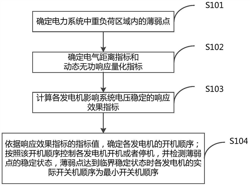
The invention provides a unit load dynamic reactive response based minimum boot order optimization method. The method comprises the steps of determining a weak spot in a heavy load region of a power system; determining an electrical distance index and a dynamic reactive response quantitative index; calculating response effect indexes influencing system voltage of each generator in the power system separately; determining the boot order of the generators according to index values of the response effect indexes; controlling the startup and shutdown of the generators based on the boot order, and detecting the steady state of the weak spot, wherein the actual startup-shutdown order of the generators when the weak spot reaches a critical steady state is the minimum boot order. Compared with the prior art, the invention provides the unit load dynamic reactive response based minimum boot order optimization method; the effect degrees for the system voltage in the shutdown processes of the generators are clearly determined, so that the generator boot order arrangement policy at the minimum machine halt mode is greatly improved, and the method is relatively high in adaptability.

Description

technical field [0001] The invention relates to the field of power systems, in particular to a method for optimizing the minimum start-up sequence based on the dynamic reactive power response of unit loads. Background technique [0002] The large receiving end system of the power system mainly realizes supply and demand balance by accepting active power input from external and remote power sources. The installed capacity of the power supply of the receiving end system itself is insufficient, and the operation mode of small start-up and heavy load makes the voltage stability of the large receiving end grid prominent. Voltage stability is a local stability problem. Its essence lies in the voltage drop caused by large-scale transmission of reactive power. Especially in the case of reactive power reserve tension, the voltage level is generally difficult to meet the requirements. The operating guidelines also require that reactive power compensation should meet the requirements of...

Claims


Application Information

Patent Timeline
Patent Type & Authority Patents(China)
IPC IPC(8): H02J3/16
CPCH02J3/001H02J3/16Y02E40/30
Inventor 党杰张文朝奚江惠潘晓杰徐友平潘艳刘兵陆勇王少博
Owner STATE GRID CORP OF CHINA
Learn More