
Microwave energy receiving flat panel capable of absorbing linearly polarized incident wave in random direction

An energy receiving technology in any direction, applied in the direction of antenna, antenna array, radiating element structure, etc., can solve the problem of limited absorption capacity of single-polarized energy receiving device, and achieve variable structure, high aperture efficiency and good matching performance. Effect

Inactive Publication Date: 2016-05-25
ZHEJIANG UNIV +1
View PDF4 Cites 9 Cited by
  • Summary
  • Abstract
  • Description
  • Claims
  • Application Information

AI Technical Summary

Problems solved by technology

In these cases, the polarization directions of electromagnetic waves are diverse, and the absorption capacity of single-polarized energy receiving devices is limited

Method used

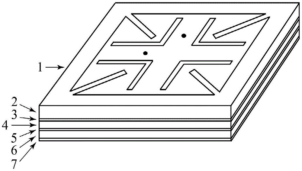
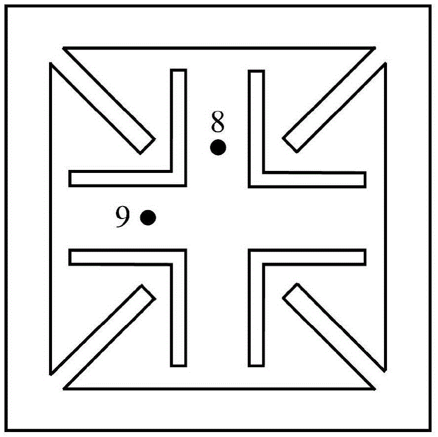
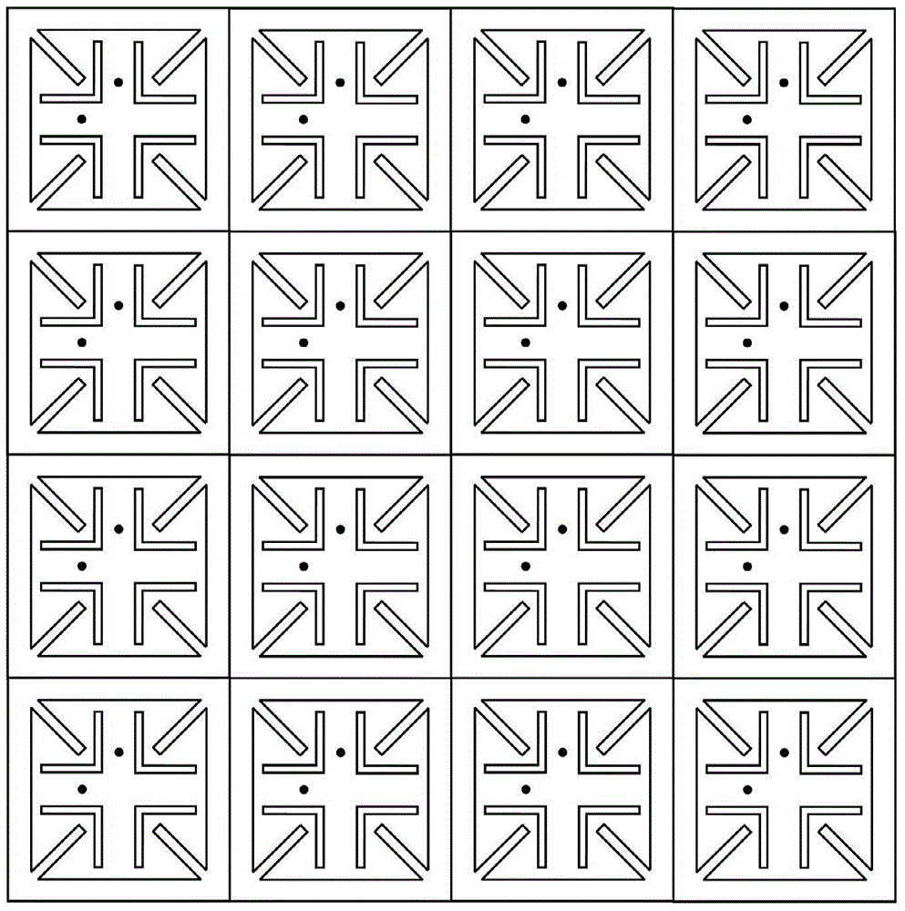

Image

  • Microwave energy receiving flat panel capable of absorbing linearly polarized incident wave in random direction
  • Microwave energy receiving flat panel capable of absorbing linearly polarized incident wave in random direction
  • Microwave energy receiving flat panel capable of absorbing linearly polarized incident wave in random direction

Examples


Embodiment Construction

[0029] Below in conjunction with accompanying drawing and specific embodiment, the present invention will be further described:

[0030] Such as figure 1 As shown, the panel of the present invention includes sub-wavelength square array units, and each square array unit is the first thin metal layer 1, the first dielectric substrate layer 2, the second thin metal layer 3, and the second dielectric substrate from top to bottom. layer 4, the third thin metal layer 5, the third dielectric substrate layer 6 and the fourth thin metal layer 7, wherein both the middle of the second dielectric substrate layer 4 and the middle of the third dielectric substrate layer 6 contain strip-shaped metal lines.

[0031] The flat plate of the present invention can be formed by periodically duplicating and extending the square array unit. In the square array unit: as figure 2 As shown, the first thin metal layer 1 is a square double-linearly polarized patch, the four corners of the patch are prov...


PUM


Abstract

The invention discloses a microwave energy receiving flat panel capable of absorbing a linearly polarized incident wave in a random direction. The microwave energy receiving flat panel is formed by continuation and arrangement of at least one sub-wavelength square array unit, wherein a square dual linearly polarized resonance structure is etched on a first thin metal layer; the first thin metal layer is formed by forming bar grooves at opposite corners and inside a patch; two metal via holes are formed in the patch; the two metal via holes pass through various middle layers and are connected with two power combining networks respectively; the two power combining networks are located in two layers of strip line structures respectively and are formed by cascading two-in-one power combining circuits; output ends of the two power combining networks are connected with two input ends of a directional coupler; two output ends of the directional coupler are connected with two rectifier circuits respectively; and the output ends of the rectifier circuits are connected in parallel such that a direct-current output is obtained. The microwave energy receiving flat panel achieves efficient receiving of linearly polarized incident electromagnetic wave energy in the random direction in the space, and can be widely applied to the fields of receiving and converting of microwave energy with various bands and power levels.

Description

technical field [0001] The invention relates to an energy receiving board, in particular to a microwave energy receiving board which absorbs linearly polarized incident waves in any direction. Background technique [0002] Microwave wireless energy transmission is a type of technology that uses vacuum or the atmosphere as the propagation medium to transmit electric energy in the form of electromagnetic waves in the far field. In the microwave energy transmission system, the receiving end receives the incident microwave energy and converts it into DC energy, which is stored and stored. use. Microwave energy transmission technology not only has broad application prospects in space solar satellite power stations, energy transmission between space aircraft and other fields, but also has received continuous attention in the energy supply of low-power sensors and electronic products in recent years. [0003] With the development of microelectronics and wireless communication tech...

Claims


Application Information

Patent Timeline
Patent Type & Authority Applications(China)
IPC IPC(8): H01Q1/38H01Q21/06
CPCH01Q1/38H01Q21/061
Inventor 陈哲达叶德信董亚洲董士伟李小军冉立新
Owner ZHEJIANG UNIV
Learn More