Eureka AIR delivers breakthrough ideas for toughest innovation challenges, trusted by R&D personnel around the world.

Test device for simulating steam generator secondary side waste heat exhaust system and method

A waste heat removal system and steam generator technology, which is applied to instruments, teaching models, educational appliances, etc., can solve problems such as poor local characteristics, unsatisfactory, and inability to meet scientific research needs, and achieves increased selectivity and guaranteed similarity. Effect

Active Publication Date: 2016-05-25
CHINA NUCLEAR POWER TECH RES INST CO LTD +2
View PDF18 Cites 24 Cited by
  • Summary
  • Abstract
  • Description
  • Claims
  • Application Information

AI Technical Summary

Problems solved by technology

[0002] The existing test device for simulating the secondary side waste heat removal system of the steam generator includes a simulation of the secondary side passive waste heat removal system based on ACP1000, which can be used to test the operating characteristics of the secondary side passive waste heat removal system and reliability test verification, but it only models the passive waste heat removal system on the secondary side of the reactor. The primary side of the steam generator uses electric heating simulation, which cannot accurately simulate the water-to-water heat exchange process between the primary and secondary loops of the reactor. need
At the same time, the existing test device for simulating the waste heat discharge system on the secondary side of the steam generator is modeled according to the power volume method. Due to the defects of the modeling method, the modeled test device shows very poor local characteristics, which cannot meet the needs of scientific research.

Method used


Image

  • Test device for simulating steam generator secondary side waste heat exhaust system and method

Examples


Embodiment Construction

[0030] In order to have a clearer understanding of the technical features, purposes and effects of the present invention, the specific implementation manners of the present invention will now be described in detail with reference to the accompanying drawings.

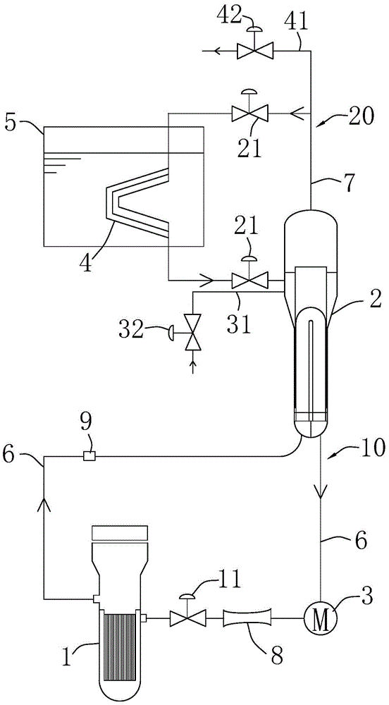
[0031] like figure 1 As shown, the test device for simulating the waste heat discharge system on the secondary side of the steam generator according to an embodiment of the present invention includes a heat source simulation body 1, a cold source simulation body 2, a final heat sink heat exchanger 4, a final heat sink water tank 5, a A pipeline 6 and a second pipeline 7; the heat source simulation body 1 and the cold source simulation body 2 are interconnected through the first pipeline 6 to form a loop 10; the final heat sink heat exchanger 4 is arranged in the final heat sink water tank 5, and the cold source simulation The body 2 and the final heat sink heat exchanger 4 are interconnected by a second pipe 6 to form a...


PUM


Abstract

The invention discloses a test device for simulating a steam generator secondary side waste heat exhaust system and a method. The test device comprises a heat source simulation body, a cold source simulation body, a final heat sink heat exchanger, a final heat sink water tank, a first pipeline and a second pipeline, wherein the heat source simulation body and the cold source simulation body are connected through the first pipeline to form a first loop, the final heat sink heat exchanger is arranged in the final heat sink water tank, the cold source simulation body and the final heat sink heat exchanger are connected through the second pipeline to form a second loop, the first loop has a first heat exchange medium, the second loop has a second heat exchange medium, the heat source simulation body heats the first heat exchange medium, and the first heat exchange medium realizes heat exchange with the second heat exchange medium in the cold source simulation body. According to the test device, the first and second loops of a reactor are taken as prototypes, an H2TS method is utilized for simulation, integral phenomena and local phenomena of the steam generator secondary side passive waste heat exhaust system can be better simulated, a water-water heat exchange process generated between the first and second loops of the reactor can be accurately simulated, and requirements are satisfied.

Description

technical field [0001] The invention relates to a thermal hydraulic test simulation device, in particular to a test device and method for simulating a secondary side waste heat discharge system of a steam generator. Background technique [0002] The existing test device for simulating the secondary side waste heat removal system of the steam generator includes a simulation of the secondary side passive waste heat removal system based on ACP1000, which can be used to test the operating characteristics of the secondary side passive waste heat removal system and reliability test verification, but it only models the passive waste heat removal system on the secondary side of the reactor. The primary side of the steam generator uses electric heating simulation, which cannot accurately simulate the water-to-water heat exchange process between the primary and secondary loops of the reactor. need. At the same time, the existing test device for simulating the waste heat removal syste...

Claims


Application Information

Patent Timeline
IPC IPC(8): G09B25/02
CPCG09B25/02
Inventor 徐海岩卢冬华吴小航文青龙李亮国
Owner CHINA NUCLEAR POWER TECH RES INST CO LTD
Why Eureka
Eureka Blog
Learn More