Supercharge Your Innovation With Domain-Expert AI Agents!

Circular pipe column and H-shaped beam connection structure

A technology for connecting structures and round pipes, applied in building structures, buildings, etc., can solve problems such as complex connections, avoid welding seam crossing, avoid stress concentration and metal fatigue, and facilitate construction.

Inactive Publication Date: 2016-05-25
POWERCHINA HUADONG ENG COPORATION LTD
View PDF16 Cites 3 Cited by
  • Summary
  • Abstract
  • Description
  • Claims
  • Application Information

AI Technical Summary

Problems solved by technology

However, unlike the H-section column, the circular tube section has no clear web and flange, so the connection between the circular tube section column and the H-section beam is more complicated

Method used


Image

  • Circular pipe column and H-shaped beam connection structure
  • Circular pipe column and H-shaped beam connection structure
  • Circular pipe column and H-shaped beam connection structure

Examples


Embodiment 1

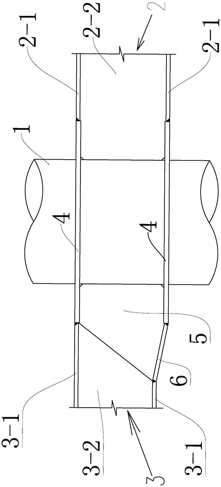
[0024] Such as figure 1 , figure 2 As shown, this example is applicable to large-diameter circular tubular columns, including vertical circular tubular column 1 and horizontal H-shaped beams on both sides of the column. In this example, there are beams I2 and beam II3, and the height of beam I2 is greater than that of beam II3. The connection between the column and the beam is through the connecting plate 4 (namely, the node member). The connecting plate 4 in this example is basically a ring plate, and the two sides are cut into straight lines. The installation position of the connecting plate 4 is the same as that of the wing The specific method is: the flange 2-1 of the beam I2 is partially cut off and then welded to the connecting plate 4 (that is, the connecting plate replaces part of the flange), and the web 2-2 of the beam I extends into the upper and lower two sides. Between the block connecting plates 4 and directly welded with the outer wall of the round pipe column...

Embodiment 2

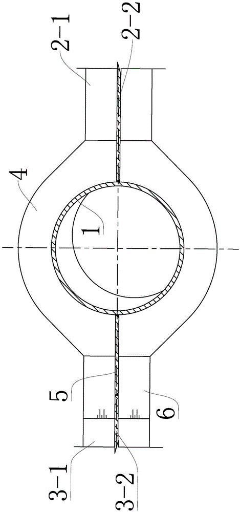
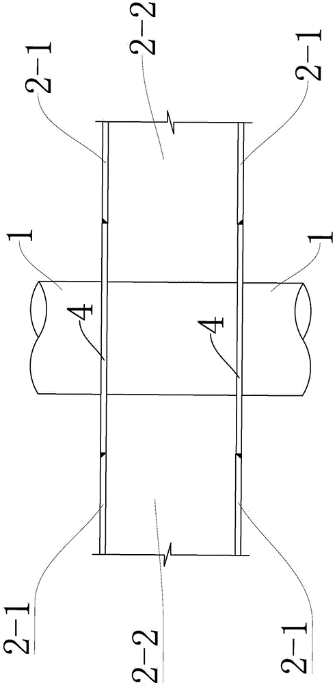
[0028] Such as image 3 , Figure 4 As shown, this example is suitable for small-diameter circular pipe columns, and the H-beams on both sides of the circular pipe column 1 are beam I2 (beam heights are equal). The connecting plate 4 is a flat plate (octagonal in this example) symmetrical on both sides, with a round hole matching the outer wall of the circular pipe column 1 left in the middle, and the installation position of the connecting plate 4 is the same as that of the two flanges 2-2 of the beam I. Corresponding to 1, the specific method is: the flange 2-1 of the beam I is partially cut off and then welded to the connecting plate 4, and the web 2-2 of the beam I extends vertically between the upper and lower connecting plates 4 and is on the central axis Butt welding at the place is firm, and two semicircular columns 1-1 are spliced ​​and welded into a complete circular tube column 1 at the center of the connecting plate 4 and symmetrically on both sides of the web 2-2...


PUM


Abstract

The invention relates to a circular pipe column and H-shaped beam connection structure. The technical scheme includes that the circular pipe column and H-shaped beam connection structure comprises a vertical circular pipe column and horizontal H-shaped beams; web plates of the H-shaped beams are consistent with the axial direction of the circular pipe column, and two flanges of each H-shaped beam are perpendicular to the axis of the circular pipe column. The circular pipe column and H-shaped beam connection structure is characterized in that the circular pipe column is connected with the H-shaped beams by connecting plates, partial flanges of the H-shaped beams are replaced by the connecting plates, the connecting plates are respectively connected with the circular pipe column and the H-shaped beams, and the web plates of the H-shaped beams are connected with the outer wall of the circular pipe column. The circular pipe column and H-shaped beam connection structure has the advantages that stress requirements on beam and column structures can be met, and the circular pipe column and H-shaped beam connection structure is easy and convenient to construct and good in anticorrosion performance; the circular pipe column and H-shaped beam connection structure is applicable to welding and connecting beams and columns of main steel structures of marine booster stations.

Description

technical field [0001] The invention relates to a connection structure between a circular pipe column and an H-shaped beam. It is suitable for welding connection between beams and columns of main steel structure of offshore booster station. Background technique [0002] The beams and columns of large-scale steel structure buildings are all made of steel structures. The cross-sections of steel columns are generally H-shaped, round tube-shaped, etc., while the cross-sections of steel beams are mostly H-shaped. The steel column with circular tubular section is a welded steel pipe or seamless steel pipe as the column structure. Due to its isotropic symmetry and large section moment of inertia, the circular tubular section is ideal as a compression structure. The main steel structure column of the station generally adopts circular tubular section column. However, unlike the H-section column, the circular tube section has no clear web and flange, so the connection between the ci...

Claims


Application Information

Patent Timeline
Patent Type & Authority Applications(China)
IPC IPC(8): E04B1/24E04B1/58
CPCE04B1/2403E04B2001/2415E04B2001/2454
Inventor 赵生校陈德春王淡善孙杏建俞华锋吕国儿贾献林黄春林汤群益徐小龙王永发
Owner POWERCHINA HUADONG ENG COPORATION LTD
Features
  • R&D
  • Intellectual Property
  • Life Sciences
  • Materials
  • Tech Scout
  • Unparalleled Data Quality
  • Higher Quality Content
  • 60% Fewer Hallucinations
Learn More