Washing machine automatic deceleration clutch

A deceleration clutch, fully automatic washing machine technology, applied in the field of washing machines, to achieve the effect of reducing noise, eliminating impact, and reducing manufacturing costs

Inactive Publication Date: 2018-06-01
NINGGUO JULONG IND
View PDF4 Cites 0 Cited by
  • Summary
  • Abstract
  • Description
  • Claims
  • Application Information

AI Technical Summary

Problems solved by technology

[0003] The technical problem to be solved by the present invention is to design a fully automatic deceleration clutch for a washing machine to solve the technical problems of improving the washing efficiency of the washing machine, reducing the noise of the washing machine, and simplifying the structure of the deceleration clutch and its operating system

Method used


Image

  • Washing machine automatic deceleration clutch
  • Washing machine automatic deceleration clutch
  • Washing machine automatic deceleration clutch

Examples


Embodiment Construction

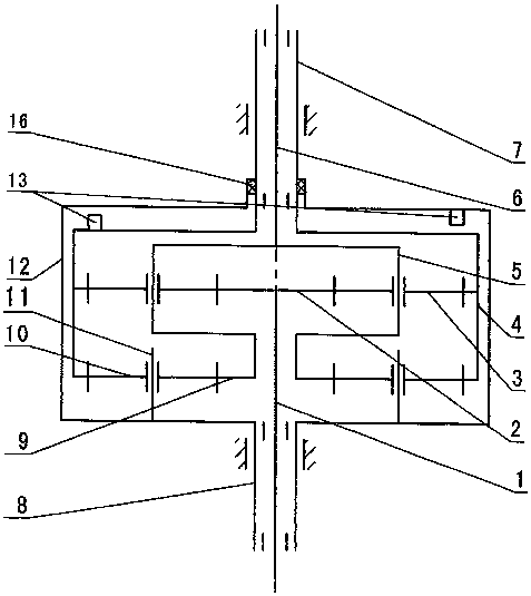
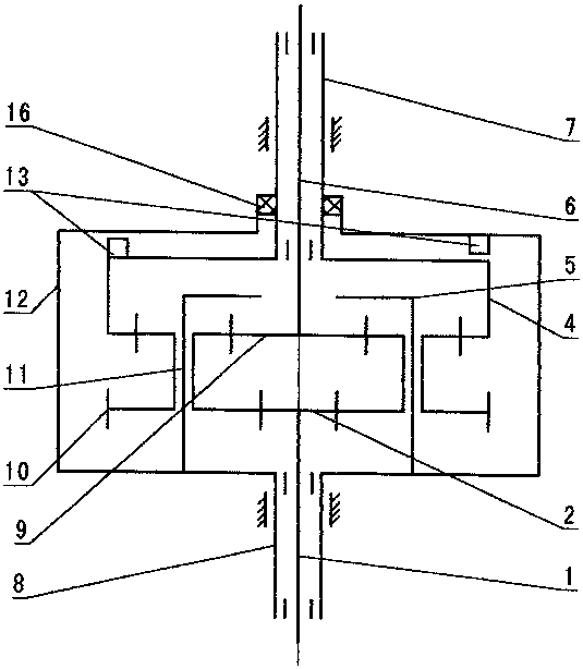
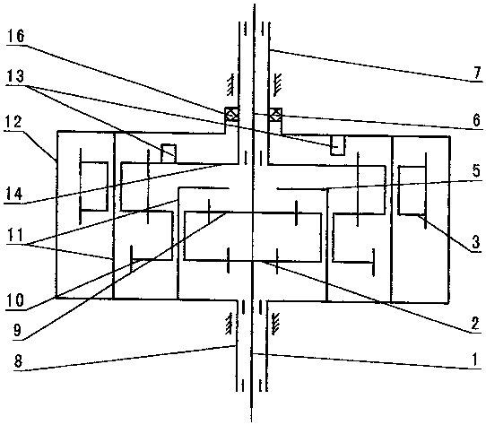
[0031] 1. Combine figure 1 The fully automatic deceleration clutch of the washing machine is composed of an input shaft 1, an output shaft 6, an output shaft sleeve 7, an input shaft sleeve 8, a brake wheel 12 and a double drive gear mechanism 15 installed inside the brake wheel 12, and the input shaft 1 is installed on In the input shaft sleeve 8, the output shaft 6 is installed in the output shaft sleeve 7, the input shaft sleeve 8 is fixed on the lower end of the brake wheel 12, the planetary shaft is fixed on the input shaft sleeve 8, the input shaft 1, the output shaft sleeve 7 And the output shaft 6 is connected with the double driving gear mechanism 15 respectively, and the clutch device 13 is housed between the brake wheel 12 and the output shaft sleeve 7. A sealing ring 16 is installed between the upper opening of the brake wheel 12 and the output shaft sleeve 7 to prevent the outside world from polluting the double drive gear mechanism 15, and also to prevent the dou...


PUM


Abstract

The invention relates to the technical field of washing machines and provides a three-stage duplex tooth outer tooth transmission mechanism of a full-automatic speed reduction clutch for a washing machine. The transmission mechanism is mainly composed of an input shaft, an output shaft, an output shaft sleeve, an input shaft sleeve, a brake wheel and a double-drive gear mechanism installed in the brake wheel. The input shaft, the output shaft sleeve and the output shaft are connected with the double drive gear mechanism. A clutch device is arranged between the brake wheel and the output shaft sleeve. In the washing process, the output shaft and the output shaft sleeve are reverse mutually, are driven in the two directions according to the ratio, swing and rotate repeatedly, and carry out rubbing and swinging oppositely with force; in the dehydrating process, by means of the locking effect of the clutch device, the output shaft and the output shaft sleeve can be combined automatically and do high-speed one-way continuous rotation. The mechanism is simple in structure, performance of the speed reduction clutch of a conventional washing machine is improved, the structure of a control system is simplified, noise of the washing machine is lowered, the effect of the washing machine is improved, and the service life of the washing machine is prolonged.

Description

Technical field: [0001] The technical solution created by the invention relates to the technical field of washing machines, in particular to the deceleration clutch of washing machines. Background technique: [0002] Existing conventional deceleration clutch mainly is made up of input shaft, output shaft, output shaft sleeve, input shaft sleeve, braking wheel, the deceleration mechanism that is installed in braking wheel inside and the clutch part that is installed on the input shaft sleeve. In the washing condition, the output shaft is required to rotate repeatedly at low speed in both directions. The output sleeve and the brake wheel of the conventional deceleration clutch are integrated, and the deceleration mechanism generally only plays a simple deceleration function. When the brake wheel is braked, the output The axle sleeve is also braked, and the two-way rotation of the transmission motor can only drive the corresponding two-way rotation of the output shaft. In the ...

Claims


Application Information

Patent Timeline
Patent Type & Authority Patents(China)
IPC IPC(8): D06F37/30F16H1/32F16D67/02
CPCD06F37/30D06F37/304D06F37/36F16D67/02F16H1/32F16H2001/327
Inventor 刘军薛华林
Owner NINGGUO JULONG IND
Why Eureka
Try Eureka