
Patsnap Eureka
For R&D, Patsnap Eureka makes reading and utilizing patents & technical documents easy.
Patsnap Eureka AIR
Designed for self-driven R&D workflows. Generate viable solutions, solve complex R&D challenges, empower your innovation with AI.

Patsnap Eureka Materials
Designed for material experts only. Revolutionize your material R&D, from search, analyze, to developing new materials.

TechResearch
Generate reliable direction feasibility study reports for your R&D in just a few steps.

TechSeek
Discover and master advanced knowledge NOW. Basics, ideas, possibilities, all at once.

TechMind
As an expert in R&D Theories, TechMind can generates customized viable solutions instantly.

TechRisk
Analyze your overall solution with one click, know your potential R&D risks in advance.

TechMonitor
Get weekly tech updates, stay abreast of the latest tech innovations and key insights.
High speed winding machine guide wire cam
A winding machine and guide wire technology, which is applied in the direction of conveying filamentous materials, thin material processing, transportation and packaging, etc., can solve the problems of increased harmful vibration and guide wire cam vibration, etc., to reduce harmful vibration and stabilize power performance effect
- Summary
- Abstract
- Description
- Claims
- Application Information
AI Technical Summary
Problems solved by technology
Method used
Image

Examples
Embodiment 1
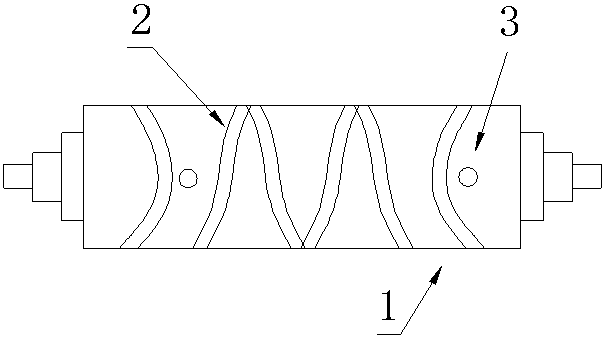
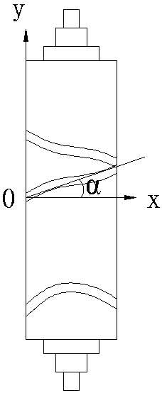
[0016] Such as figure 1 As shown, the guide wire cam of the high-speed winding machine is used on the 16-head winding head. The length of the guide wire cam is 2050mm, the diameter is 64mm, and the working speed is 6500rpm. Including the guide wire cam body 1 and the guide wire groove 2 provided on the surface of the guide wire cam body 1, a hole 3 that does not penetrate the guide wire cam is respectively provided on the surface of the guide wire cam body 1 at the two ends of the guide wire cam, and the diameter of the hole 3 is 5mm, the depth of hole 3 is 7mm, the hole 3 on the left is 54.4mm away from the left end, the hole 3 on the right is 51.2mm away from the right end, the phase angle of the left and right holes 3 is 0°, the material of guide wire cam body 1 is structural steel, and the guide wire cam body 1 is made of structural steel. The curve fitting function for rounding at the intersection of thread groove 2 is: y=0.00152832x 2 , x 0 =12.312,y 0 =2.27, α=20°18′...
Embodiment 2
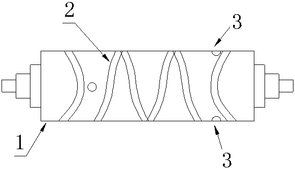
[0021] Such as image 3 As shown, the difference from Embodiment 1 is that the working speed of the guide wire cam is 8000rpm, the diameter of the hole 3 is 7mm, the depth of the hole 3 is 10mm, the distance between the hole 3 on the left side is 35.22mm from the left end, and the hole 3 on the right side is provided with Two, respectively 38.52mm and 44.36mm away from the right end, and the three-phase angle of the left and right holes is 90°.
Embodiment 3
[0023] Such as Figure 4 As shown, the difference from Embodiment 1 is that the diameter of the guide wire cam is 74 mm, the working speed is 7000 rpm, the diameter of the hole 3 is 6 mm, and the depth of the hole 3 is 8 mm. The natural frequency and corresponding rotational speed under φ74 are shown in Table 2:
[0024]
[0025] There are two holes 3 on the left side, 49.0mm and 53.3mm away from the left end respectively, and the hole 3 on the right side is 38.9mm away from the right end, and the angle between the left and right holes 3 is 0°.
PUM
 Abstract
Description
Claims
Application Information
 - R&D Engineer
- R&D Manager
- IP Professional
- Industry Leading Data Capabilities
- Powerful AI technology
- Patent DNA Extraction
Browse by: Latest US Patents, China's latest patents, Technical Efficacy Thesaurus, Application Domain, Technology Topic, Popular Technical Reports.
© 2024 PatSnap. All rights reserved.Legal|Privacy policy|Modern Slavery Act Transparency Statement|Sitemap|About US| Contact US: help@patsnap.com