
A back blowing dust removal system

A soot cleaning and channel technology, which is applied in the fields of dispersed particle filtration, membrane filter, gas treatment, etc., can solve the problems of complex structure, high cost and waste of air flow in the soot blowing system, and achieve good cleaning effect, high air flow, simple structure

Active Publication Date: 2018-03-06
南通鑫萍复合材料科技有限公司
View PDF5 Cites 0 Cited by
  • Summary
  • Abstract
  • Description
  • Claims
  • Application Information

AI Technical Summary

Problems solved by technology

[0008] This method of utilizing the airflow provided by its own air pump to carry out dust removal, will also reclaim the blown air while the airflow is being blown back in the filter device, otherwise the dust will be discharged from the ash suction port 47, which is wasteful. A large part of the airflow, coupled with the low air pressure generated by the air pump itself, the flow rate is slow, and the soot blowing effect is not ideal
Moreover, this kind of soot blowing system has complex structure, high cost and short service life.

Method used


Image

  • A back blowing dust removal system
  • A back blowing dust removal system
  • A back blowing dust removal system

Examples


Embodiment Construction

[0035] In the following, the technical solution of a back-blowing dust-cleaning system involved in the present invention will be further described in detail with reference to the drawings and embodiments.

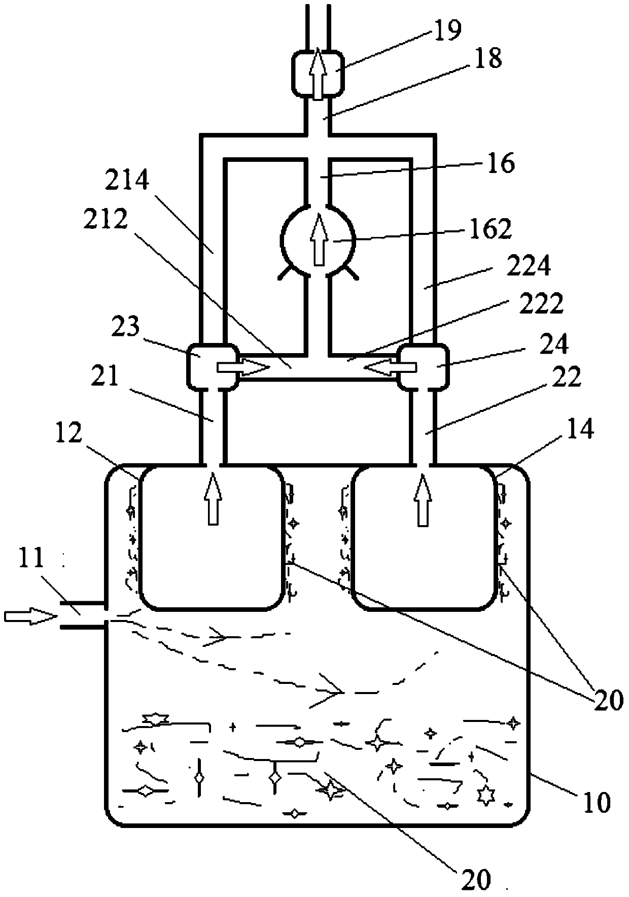
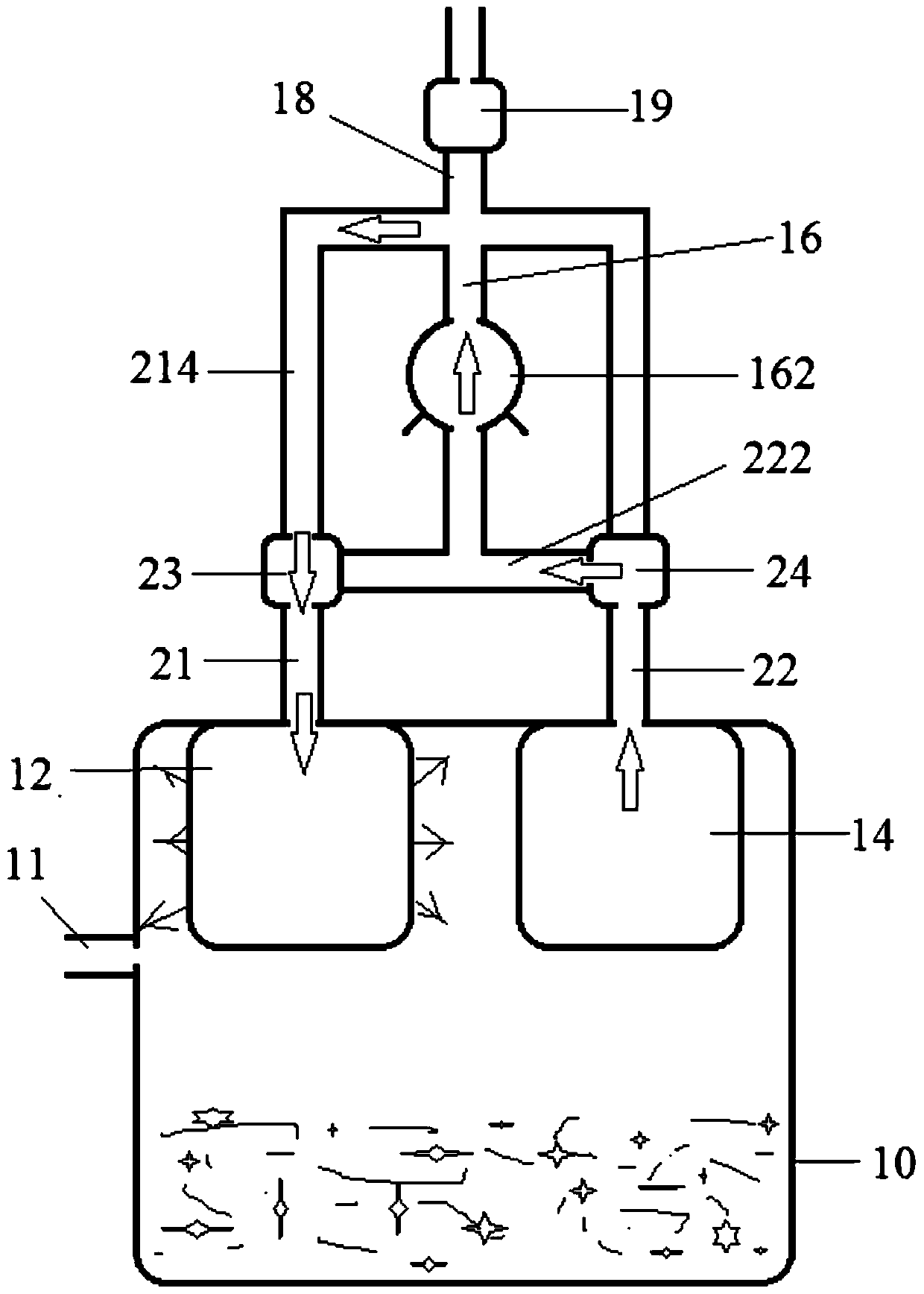
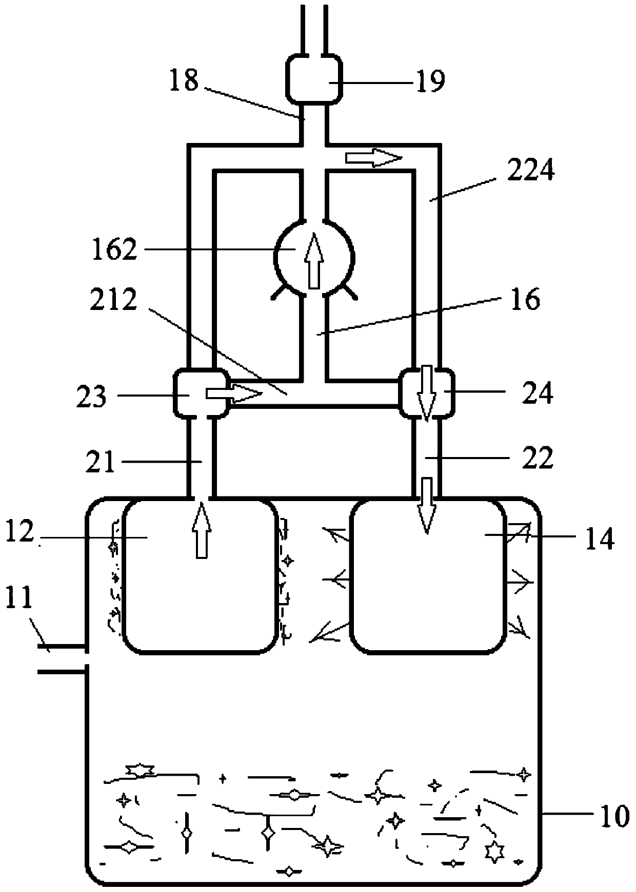
[0036] see figure 1 As shown, an embodiment of the present invention provides a reverse blowing dust cleaning system, which includes a first channel 21 , a second channel 22 , a fan channel 16 , and an exhaust channel 18 . One end of the first channel 21 and the second channel 22 are respectively used to connect the first filter device 12 and the second filter device 14 , and the fan channel 16 is provided with a fan 162 .

[0037] Wherein the first channel 21 and the second channel 22 are further provided with a first valve 23 and a second valve 24 respectively. And the first passage 21 leads out from the first valve 23 to the first branch 212 and the second branch 214, and the second passage 22 leads out from the second valve 24 to the third branch 222 and the second br...


PUM


Abstract

The present invention provides a back blowing dust cleaning system, which includes a first channel, a second channel, and an exhaust channel, and one end of the first channel and the second channel is respectively used to connect the first filter device and the second filter device . Wherein the first channel and the second channel are respectively provided with a first valve and a second valve, and by setting the first valve and the second valve, the communication between the first channel and the second channel is made, Or make the first channel communicate with the second channel and the exhaust channel.

Description

technical field [0001] The invention relates to a back-blowing dust cleaning system, which is applicable to filters in dust suction, smoking, oil suction and filter systems, and the outer wall of the dust cleaning system is attached to the filter. Background technique [0002] In order to effectively remove garbage in the environment, maintain environmental sanitation, and also have high removal efficiency, vacuum cleaners have been developed. Due to different environments, the cleaning requirements are also different. In order to carry out targeted and effective cleaning, the industry has developed many different types of vacuum cleaners for cleaning in different types of environments. [0003] These commonly used vacuum cleaners are usually equipped with filtering devices for filtering the exhausted airflow, so as to filter out the remaining dust or other fine debris in the exhausted airflow to prevent secondary pollution. These filter devices, after a long period of use,...

Claims


Application Information

Patent Timeline
Patent Type & Authority Patents(China)
IPC IPC(8): B01D46/00B01D46/24B01D46/42
CPCB01D46/2411B01D46/42B01D2258/06B01D2279/55B01D46/58
Inventor 金建华韩胜杰
Owner 南通鑫萍复合材料科技有限公司
Learn More