
Lightguide tamper seal

A technology of anti-tampering and sealing parts, which is applied in the directions of seals, instruments, closures, etc., can solve the problems of impossibility and impracticality, and achieve the effect of avoiding the loss of light transmission

Active Publication Date: 2016-05-18
CSEM CENT SUISSE DELECTRONIQUE & DE MICROTECHNIQUE SA RECH & DEV
View PDF20 Cites 4 Cited by
  • Summary
  • Abstract
  • Description
  • Claims
  • Application Information

AI Technical Summary

Problems solved by technology

This may be highly impractical or practically impossible to implement in most anti-counterfeiting control situations that will occur in harsh environments or must be performed within a very limited time period

Method used


Image

  • Lightguide tamper seal
  • Lightguide tamper seal
  • Lightguide tamper seal

Examples


Embodiment Construction

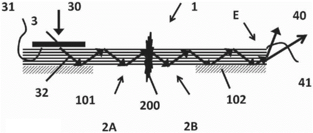
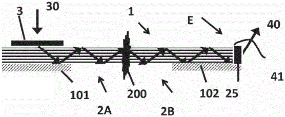
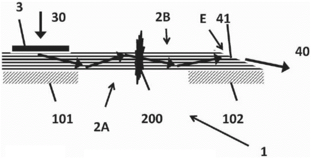
[0050] The following detailed description illustrates principles and examples consistent with the invention. It is thus to be appreciated that those skilled in the art can devise various arrangements which, although not explicitly described or shown, embody the general principles of the invention and which are included within the scope as defined by the claims. In the specification and drawings, like reference numerals designate the same or similar components or structural elements. Also, as the term is used herein to describe "transparent", an average visible light transparency of at least 70% of the light beam is achieved for light of the wavelength of interest. As used herein, the term "visible light" refers to light between near ultraviolet and near infrared (i.e., between 300nm-2μm), since such wavelengths can be seen by the human eye or can be easily converted to wavelengths visible to the human eye .

[0051] According to the invention, the tamper seal 1 comprises an ...


PUM


Abstract

The invention concerns a tamper seal (1) comprising an optical waveguide (2) arranged to guide a propagating light-beam along a propagation direction, comprising at least a first portion (2A) and a second portion (2B) intended to be respectively arranged on a first part and on a second part of an object, said first and a second parts being movable relative to each other. Said optical waveguide (2) is a multimode waveguide comprising at least a waveguide core that has its smallest dimension, defined perpendicular to said propagation direction, greater than 10 [mu]m and smaller than 10mm. Said first portion (2A) comprises an input coupler (3) arranged to couple incident light into said optical waveguide (2) and wherein said second portion (2B) comprises at least one outcoupling surface arranged to couple out at least partially light guided in the optical waveguide (2). Said input coupler (3), said optical waveguide (2) and said outcoupling surface are arranged so as to transmit light from said input coupler (3) to said outcoupling surface, said optical waveguide (2) being further designed to be at least partially disruptable between said two portions, said optical waveguide (2) losing or changing at least partially its optical guiding properties after its disruption.

Description

technical field [0001] The present invention relates to the field of tamper-evident seals for detecting fraudulent manipulation and counterfeiting of valuable goods or products. The invention relates more particularly to the field of visual tamper seals or electromagnetic tamper seals. Background technique [0002] Counterfeiting is extremely harmful to customers who are deceived, and counterfeiting is especially harmful to the industry as the product loses credibility and in turn brands can lose a lot of volume due to this type of fraud. In specific cases, such as chemicals and beverages, counterfeiting can also lead to serious safety and health risks. [0003] Proving whether a product is authentic has been an ongoing area of ​​research. For over a century, increasingly complex tamper evident seals have been devised to avoid the sale of containers, envelopes, bottles and boxes with unintended contents. The purpose of a tamper seal is to clearly show whether a container ...

Claims


Application Information

Patent Timeline
Patent Type & Authority Applications(China)
IPC IPC(8): G09F3/03
CPCG09F3/0376G09F3/03B65D55/026B65D55/066
Inventor 纪尧姆·巴塞马克·史尼柏
Owner CSEM CENT SUISSE DELECTRONIQUE & DE MICROTECHNIQUE SA RECH & DEV
Learn More