
Method for monitoring acting force between mold and member by fiber grating sensor

A fiber grating and sensor technology, which is applied in the measurement of force, the measurement of force by measuring the change of optical properties of materials when they are stressed, and instruments, etc. The problem of the force of composite material components, etc., to achieve the effect of stable and reliable measurement value, high accuracy and good repeatability

Inactive Publication Date: 2016-05-18
WUHAN UNIV OF TECH
View PDF6 Cites 3 Cited by
  • Summary
  • Abstract
  • Description
  • Claims
  • Application Information

AI Technical Summary

Problems solved by technology

Chinese patent 200910011933 "Fiber Bragg Grating Monitoring Method for Residual Strain of Composite Material Solidification" only provides a method for monitoring residual strain inside composite material components, without considering the force between the mold and composite material components
Foreign Kaushik et al. proposed a method for testing the static and sliding friction coefficient between mold components, which only explained the reason why the friction coefficient changes with the progress of the curing process, and did not provide an effective monitoring method for the mold-component force

Method used


Image

  • Method for monitoring acting force between mold and member by fiber grating sensor
  • Method for monitoring acting force between mold and member by fiber grating sensor
  • Method for monitoring acting force between mold and member by fiber grating sensor

Examples


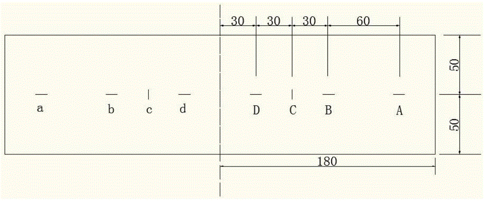
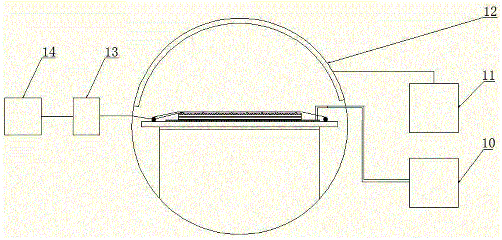
Embodiment Construction

[0028] In order to make the object, technical solution and advantages of the present invention clearer, the present invention will be further described in detail below in conjunction with the accompanying drawings and embodiments. It should be understood that the specific embodiments described here are only used to explain the present invention, not to limit the present invention.

[0029] In the embodiment of the present invention, a method for monitoring the force between a mold and a component by a fiber grating sensor is provided. The method includes the following steps. Molding material (carbon fiber prepreg layup), mold plate, optical fiber grating, and the above-mentioned FEP film layer, CFRP component preforming material (carbon fiber prepreg layup), mold plate, and optical fiber grating are integrated with a vacuum bag Sealing, the pigtail at one end of the fiber grating is connected to the fiber grating demodulator; step 2, the preformed material of the CFRP componen...


PUM

PropertyMeasurementUnit
Thicknessaaaaaaaaaa
Center wavelengthaaaaaaaaaa

Abstract

The invention discloses a method for monitoring an acting force between a mold and a member by a fiber grating sensor. A basis is laid for quantitative research of the processes of accumulation and change of a residual stress of composite materials. When the acting force between the mold and the member in the forming process of the composite materials is monitored, the method includes following steps: firstly, an FEP thin film layer, a CFRP member pre-forming material, a mold plate, and a fiber grating sensor are laid on a support mold in sequence, and sealed via a vacuum bag; secondly, the fiber grating sensor is connected with a demodulation instrument, the forming is performed by employing the autoclave process, and the fiber grating sensor monitors the curing process strain in real time; and thirdly, acquired data is processed, and the debond stress and the sliding friction stress between the mold and the member are finally calculated. According to the method, the acting force between different molds and members in the forming process of autoclaves can be tested, the operation is simple, real-time monitoring is realized, and the accuracy is high.

Description

technical field [0001] The invention belongs to the field of evaluating the mechanical properties of composite materials, and in particular relates to a method for monitoring the force of a mold and a component by an optical fiber grating sensor. Background technique [0002] Carbon fiber reinforced composite (CFRP) components have been widely used in the aerospace field because of their excellent performance. However, the dimensional stability of the components is poor, adding time and cost to assembly. The residual stress generated by CFRP during the curing molding process will cause component deformation and affect the size of the material component. Correctly understand the formation process of residual stress, predict the deformation of CFRP components, and use this part of the deformation to make the final size of CFRP components meet the assembly requirements by modifying the mold and other means, which can greatly save manufacturing costs. [0003] Many factors aff...

Claims


Application Information

Patent Timeline
IPC IPC(8): G01L1/24
CPCG01L1/242
Inventor 王继辉张盛孙亮亮刘海阳
Owner WUHAN UNIV OF TECH
Learn More