
A motor controller

A motor controller and controller technology, applied in the direction of cooling/ventilation/heating transformation, etc., can solve the problems that do not conform to the development trend of low cost and small size of motor vehicles, affect the operating efficiency of motor controllers, occupy the space of motor vehicles, etc. , to achieve ideal cooling effect, simple structure and low cost

Active Publication Date: 2018-01-05
ZHONGSHAN BROAD OCEAN
View PDF16 Cites 3 Cited by
  • Summary
  • Abstract
  • Description
  • Claims
  • Application Information

AI Technical Summary

Problems solved by technology

[0002] In a traditional hybrid vehicle, if you need to control the drive motor and generator, you need to equip two inverter modules in the electric vehicle, and control the operation of the drive motor and generator through the inverter modules, but two inverter modules require two A motor controller, which will inevitably occupy the limited space in the motor car, and the cost is relatively high, which does not conform to the current development trend of low cost and small size of the motor car, this structure will inevitably be eliminated
[0003] Now gradually there is a motor controller structure that integrates two inverter modules in one motor controller. The capacitor module is installed at the back end of the motor controller, and the two inverter modules are stacked and installed at the front end of the motor controller. The space occupied by the motor controller structure is relatively large, and the heat dissipation effect is not ideal. It is difficult to dissipate heat from the capacitor module and the two inverter modules by relying on the cooling on the bottom surface of the motor controller. If the heat dissipation problem cannot be effectively solved, it is bound to Affect the operating efficiency of the motor controller. If the temperature is too high, there may even be a safety accident. Therefore, there is an urgent need to solve the heat dissipation problem of the motor controller integrated with two inverter modules.

Method used


Image

  • A motor controller
  • A motor controller
  • A motor controller

Examples


Embodiment 1

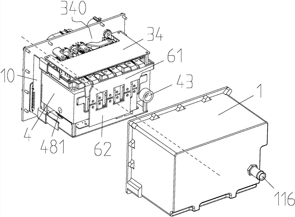
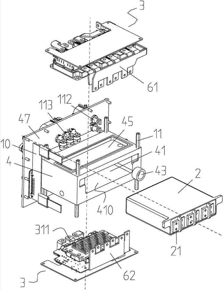
[0035] Embodiment one: if Figure 1 to Figure 9 As shown, the present invention is a motor controller, including a controller box 1, a capacitor module 2 and two inverter modules 3, a radiator 4 is installed inside the controller box 1, and a radiator 4 is provided in the middle of the radiator 4 The cavity 41, the capacitor module 2 is installed inside the cavity 41, the two inverter modules 3 are installed on the top and the bottom of the radiator 4 respectively, and a cooling water channel 42 is opened on the radiator 4 and is provided with a cooling channel 42 communicating with the cooling channel 42. The water inlet 43 and the water outlet 44 of the cooling water channel 42 dissipate heat to the capacitor module 2 and the two inverter modules 3 . The inverter module 3 includes an IGBT module 32 , a drive circuit board 33 and a control circuit board 34 , and the drive circuit board 33 and the control circuit board 34 are installed on the top surface of the IGBT module 32 ...


PUM


Abstract

Disclosed is a motor controller, comprising a controller case body (1), a capacitor module (2) and two inverter modules (3); a heat dissipating device (4) is arranged in the controller case body, a cavity (41) is formed in the middle of the heat dissipating device, the capacitor module is mounted in the cavity, the two inverter modules are mounted above and below the heat dissipating device respectively; the heat dissipating device is provided with a cooling water passage (42) and is provided with a water inlet (43) and a water outlet (44) which are in communication with the cooling water passage, the cooling water passage being used to dissipate heat from the capacitor module and from the two inversion modules. The motor controller incorporates two inverter modules, is simple and compact in structure, is relatively low in costs, and can effectively dissipate heat from the inverter modules and the capacitor module, the heat dissipating effect being ideal, and the operation of the motor controller stable and reliable.

Description

Technical field: [0001] The invention relates to a motor controller and belongs to the field of electric vehicles. Background technique: [0002] In a traditional hybrid vehicle, if you need to control the drive motor and generator, you need to equip two inverter modules in the electric vehicle, and control the operation of the drive motor and generator through the inverter modules, but two inverter modules require two A motor controller, which will inevitably occupy the limited space inside the motor car, and the cost is relatively high, does not conform to the current development trend of low cost and small size of the motor car, and this structure will inevitably be eliminated. [0003] Now gradually there is a motor controller structure that integrates two inverter modules in one motor controller. The capacitor module is installed at the back end of the motor controller, and the two inverter modules are stacked and installed at the front end of the motor controller. The...

Claims


Application Information

Patent Timeline
Patent Type & Authority Patents(China)
IPC IPC(8): H05K7/20
CPCH05K7/20
Inventor 黄风太贝特朗罗伯特莫尔
Owner ZHONGSHAN BROAD OCEAN
Learn More