Optical line terminal, optical path detection method and optical network system
A technology of optical line terminal and optical fiber network, which is applied in the field of optical communication and can solve problems such as the limitation of OLT integration.
- Summary
- Abstract
- Description
- Claims
- Application Information
AI Technical Summary
Problems solved by technology
Method used
Image


Examples
Embodiment 1
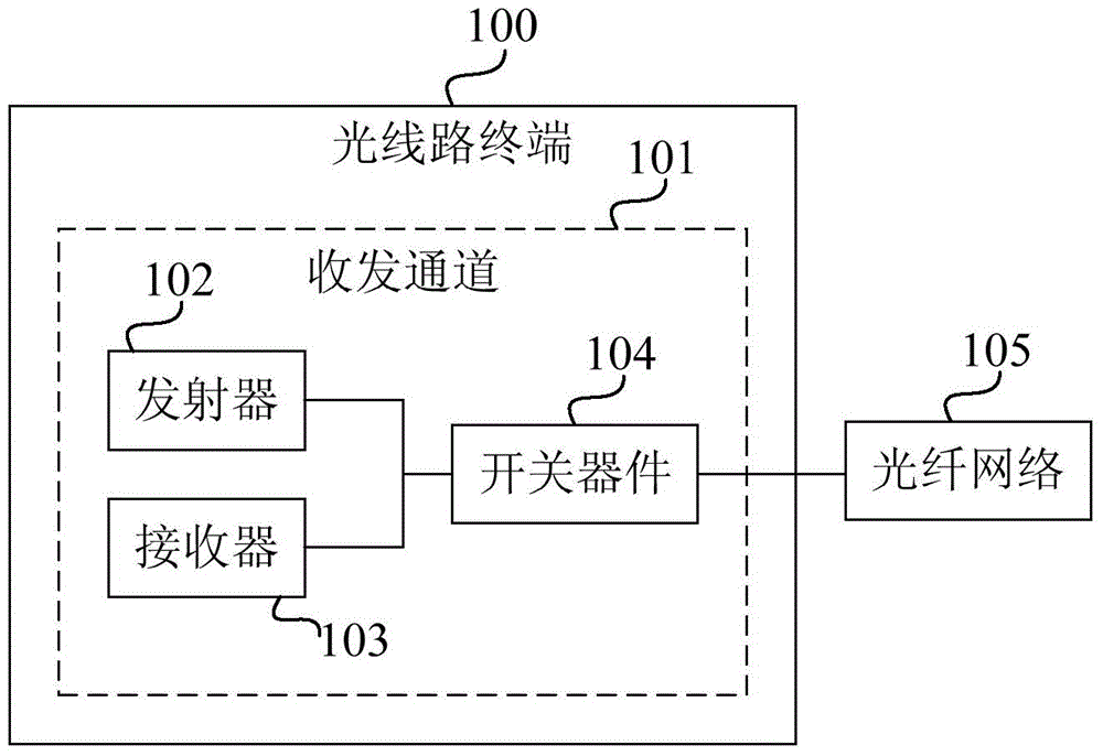
[0079] figure 1 It is a schematic structural diagram of an optical line terminal provided by Embodiment 1 of the present invention. The optical line terminal of this embodiment can be used in a PON to perform fault diagnosis on a passive ODN and perform ODN operation and maintenance. The optical line terminal can be realized by combining hardware and software. Such as figure 1 As shown, the optical line terminal 100 of this embodiment includes: at least one transceiver channel 101 . Wherein, each transceiver channel 101 includes: a transmitter 102 , a receiver 103 and a switching device 104 . The transmitter 102 and the receiver 103 are respectively connected to the optical fiber network 105 through the switch device 104 .
[0080] The switching device 104 is configured to control the optical line terminal 100 to switch between the working mode and the testing mode.
[0081] The transmitter 102 is configured to transmit a downlink data optical signal to the optical fiber ...
Embodiment 2
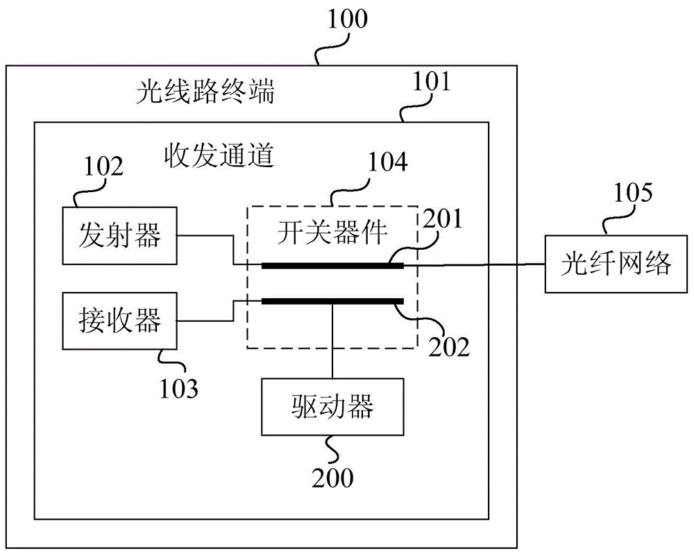
[0095] The embodiment of the present invention also provides an optical line terminal. figure 2 It is a schematic structural diagram of an optical line terminal provided by Embodiment 2 of the present invention. The solution of this embodiment is based on the solution of the above embodiments. Optionally, the switch device 104 is also used to control the optical line terminal 100 in the working mode if it is switched to a wavelength division multiplexing (WavelengthDivisionMultiplexing, referred to as WDM) device. If it is switched to an optical coupler (Optical Coupler, OC for short), the optical line terminal is controlled to be in the test mode.
[0096] Specifically, the downlink data optical signal sent by the transmitter 102 received by the switch device 104 when the optical line terminal 100 is in the working mode and the uplink data optical signal sent to the receiver 103 are respectively optical signals of different wavelengths. The isolation between the downlink da...
Embodiment 3
[0130] The embodiment of the present invention also provides an optical path detection method. The method may be executed by the optical line terminal described in any one of the first or second embodiments above. Image 6 It is a flow chart of the optical path detection method provided by the third embodiment of the present invention. Such as Image 6 As shown, the method includes the following steps:
[0131] Step 601, control the optical line terminal to switch between the working mode and the test mode through the switching device of the optical line terminal.
[0132] Step 602: If the optical line terminal is in the working mode, transmit the downlink data optical signal to the optical fiber network through the transmitter of the optical line terminal, and receive the uplink data optical signal transmitted by the optical fiber network through the receiver of the optical line terminal.
[0133] Step 603, if the optical line terminal is in the test mode, transmit a test ...
PUM
| Property | Measurement | Unit |
|---|---|---|
| Wavelength | aaaaa | aaaaa |
Abstract
Description
Claims
Application Information
 - R&D
- Intellectual Property
- Life Sciences
- Materials
- Tech Scout
- Unparalleled Data Quality
- Higher Quality Content
- 60% Fewer Hallucinations
Browse by: Latest US Patents, China's latest patents, Technical Efficacy Thesaurus, Application Domain, Technology Topic, Popular Technical Reports.
© 2025 PatSnap. All rights reserved.Legal|Privacy policy|Modern Slavery Act Transparency Statement|Sitemap|About US| Contact US: help@patsnap.com