
Intelligent power module and air conditioner

A technology of intelligent power module and power switch tube, which is applied in the output power conversion device, the conversion of AC power input to DC power output, electrical components, etc. An effect that reduces the chance of false triggers

Active Publication Date: 2016-05-11
GD MIDEA AIR-CONDITIONING EQUIP CO LTD +1
View PDF4 Cites 5 Cited by
  • Summary
  • Abstract
  • Description
  • Claims
  • Application Information

AI Technical Summary

Problems solved by technology

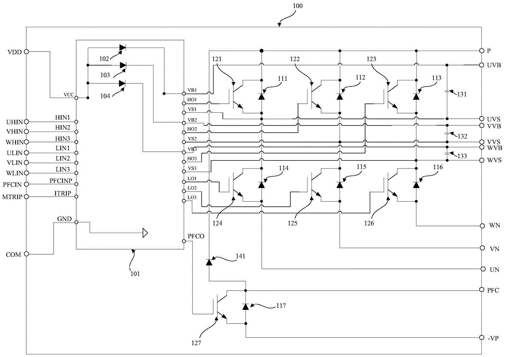
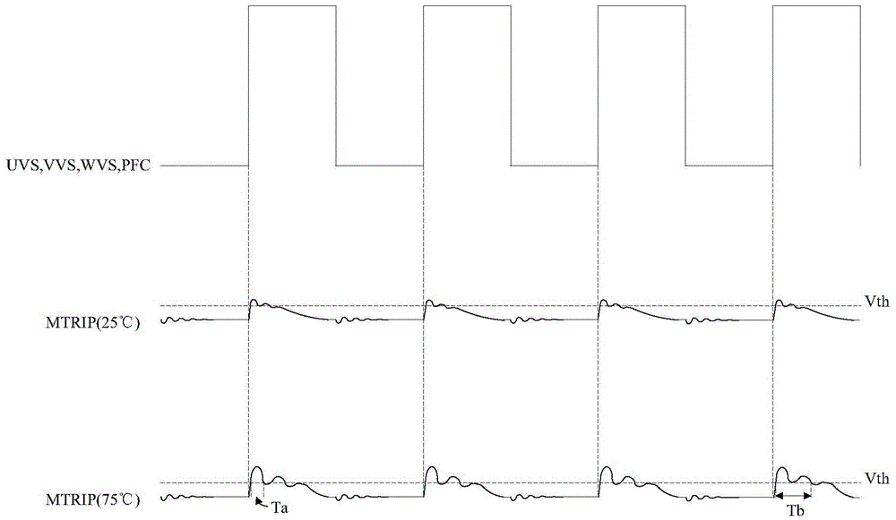
Moreover, when the temperature is higher, it is generally when the inverter part and the power correction part of the smart power module switch more frequently, so as the system continues to work, the temperature of the smart power module 100 continues to rise, and the probability of MTRIP being triggered In some harsh applications, false triggers will eventually occur and the system will stop working
Although this false trigger will recover after a period of time without causing damage to the system, it will undoubtedly cause confusion for users
For example, in the application of inverter air conditioners, the higher the ambient temperature is, the more the user needs the continuous operation of the air conditioning system, but the high ambient temperature will increase the reverse recovery time of the FRD tube, and the probability of MTRIP being falsely triggered will increase. When MTRIP is triggered by mistake, the air conditioning system will stop working for 3 to 5 minutes due to the mistaken belief that overcurrent has occurred, so that users cannot obtain cold air during this period. This is one of the main reasons why the air conditioning system receives complaints from customers due to insufficient cooling capacity.

Method used


Image

  • Intelligent power module and air conditioner
  • Intelligent power module and air conditioner
  • Intelligent power module and air conditioner

Examples


Embodiment Construction

[0052] In order to understand the above-mentioned purpose, features and advantages of the present invention more clearly, the present invention will be further described in detail below in conjunction with the accompanying drawings and specific embodiments. It should be noted that, in the case of no conflict, the embodiments of the present application and the features in the embodiments can be combined with each other.

[0053] In the following description, many specific details are set forth in order to fully understand the present invention. However, the present invention can also be implemented in other ways different from those described here. Therefore, the protection scope of the present invention is not limited by the specific details disclosed below. EXAMPLE LIMITATIONS.

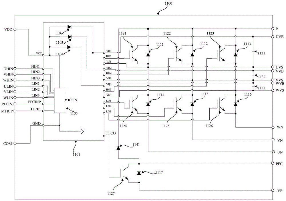
[0054] image 3 A schematic structural diagram of an intelligent power module according to an embodiment of the present invention is shown.

[0055] Such as image 3 As shown, the intelligent powe...


PUM


Abstract

The invention provides an intelligent power module and an air conditioner. An HVIC transistor in the intelligent power module is provided with a first port corresponding to a current detection end and a second port corresponding to a PFC control input end; first, second and third input ends of a self-adaption circuit are connected to three-phase upper bridge arm signal input ends respectively, fourth, fifth and sixth input ends thereof are connected to three-phase lower bridge arm signal input ends respectively, a seventh input end is connected to the second port, an eighth input end is connected to the first port, and an output end thereof serves as an enablement end of the HVIC transistor; when the input signals of the first-seventh input ends are low levels, the self-adaption circuit outputs corresponding level signals according to the relation between the input signal of the eighth input end and a first set value; and when input signal of at least one input end in the first-seventh input ends is high level, the self-adaption circuit outputs corresponding level signals according to the temperature of the intelligent power module and the relation between the input signal of the eighth input end and a second set value, wherein the second set value is larger than the first set value.

Description

technical field [0001] The present invention relates to the technical field of intelligent power modules, in particular to an intelligent power module and an air conditioner. Background technique [0002] Intelligent Power Module (Intelligent Power Module, referred to as IPM) is a power driver that integrates power electronic discrete devices and integrated circuit technology. and other fault detection circuits. The logic input terminal of the intelligent power module receives the control signal of the main controller, and the output terminal drives the compressor or subsequent circuits to work, and at the same time sends the detected system status signal back to the main controller. Compared with traditional discrete solutions, intelligent power modules have the advantages of high integration, high reliability, self-test and protection circuits, etc., and are especially suitable for inverters and various inverter power supplies for driving motors. Ideal power electronic d...

Claims


Application Information

Patent Timeline
Patent Type & Authority Applications(China)
IPC IPC(8): H02M7/5387
CPCH02M7/5387
Inventor 冯宇翔
Owner GD MIDEA AIR-CONDITIONING EQUIP CO LTD
Learn More