Inter-axle power distribution device for fixed-axle hybrid electric vehicle
A hybrid vehicle and power distribution technology, applied in transmissions, transmission parts, gear transmissions, etc., can solve the problems of high cost of transformation, power interruption, not a low-cost solution, etc., to reduce costs, avoid interference, The effect of convenient vehicle layout
- Summary
- Abstract
- Description
- Claims
- Application Information
AI Technical Summary
Problems solved by technology
Method used
Image
Examples
Embodiment 1
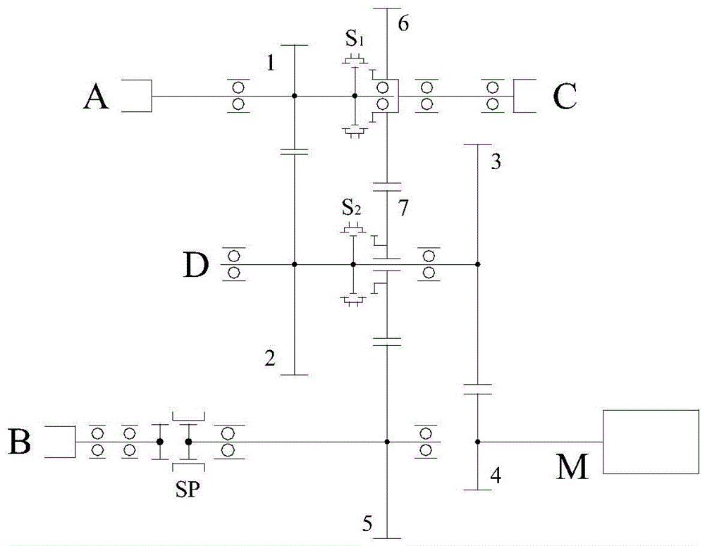
[0046] This embodiment provides an inter-axle power distribution device for a fixed-axis hybrid electric vehicle, such as figure 1 As shown, it includes a first input shaft A, a second input shaft M, a first output shaft B, a second output shaft C and an intermediate shaft D, wherein the first input shaft A is drivingly connected to the engine through the output side of the transmission; The two input shafts M are drivingly connected to the motor; the first output shaft B and the second output shaft C are respectively drivingly connected to the drive axle of the vehicle; the first input shaft A, the second input shaft M, the first output shaft B and the second output shaft The shafts C are connected to the intermediate shaft D through gear pairs respectively, and the first input shaft A, the second input shaft M, the first output shaft B and the second output shaft C are arranged between the first input shaft A or / and the middle The synchronous switching mechanism on the shaft...
Embodiment 2
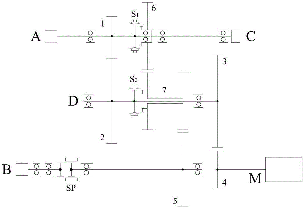
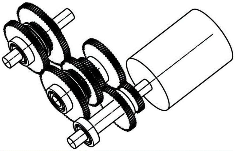
[0056] The structure of the inter-axle power distribution device for fixed-axis hybrid electric vehicles provided in this embodiment is as follows: figure 2 As shown, its difference from Embodiment 1 is that the intermediate shaft idler gear 7 is replaced by a duplex gear, and the structure of the duplex gear is as follows image 3 shown.
Embodiment 3
[0058] The structure of the inter-axle power distribution device for fixed-axis hybrid electric vehicles provided in this embodiment is as follows: Figure 4 As shown, the synchronous switching mechanism is a sliding tooth sleeve SL arranged on the first input shaft A, and the intermediate shaft D is respectively connected to the first output shaft consolidation gear 5 and the first output shaft through the low gear side of the intermediate shaft double idler gear 8 The second output shaft consolidation gear 6 meshes. All the other are with embodiment 1.
[0059] The motor is connected with the engine through gear 4 / 3 / 2 / 1 with a fixed speed ratio.
[0060] When the SL moves to the right so that the A-axis and the C-axis are connected, part of the coupling power of the two power sources is directly transmitted to the C-axis, and the rest is transmitted to the B-axis through the gear 6 / 8 / 5, thus forming two power sources High speed ratio sourced to B-axis and C-axis.
[0061]...
PUM
 Abstract
Description
Claims
Application Information
 - Generate Ideas
- Intellectual Property
- Life Sciences
- Materials
- Tech Scout
- Unparalleled Data Quality
- Higher Quality Content
- 60% Fewer Hallucinations
Browse by: Latest US Patents, China's latest patents, Technical Efficacy Thesaurus, Application Domain, Technology Topic, Popular Technical Reports.
© 2025 PatSnap. All rights reserved.Legal|Privacy policy|Modern Slavery Act Transparency Statement|Sitemap|About US| Contact US: help@patsnap.com


