
Torque overload protection tool

An overload protection and tool technology, which is applied in drilling equipment, earthmoving, driving devices for drilling in wellbore, etc. The effect of meeting the needs of on-site use, saving tripping time, and reducing operating costs

Inactive Publication Date: 2016-05-11
SOUTHWEST PETROLEUM UNIV
View PDF6 Cites 6 Cited by
  • Summary
  • Abstract
  • Description
  • Claims
  • Application Information

AI Technical Summary

Problems solved by technology

During the drilling process, different formations exert different resistances on the drill bit. This resistance makes the torque transmitted by the drill string exceed the normal drilling torque, which may cause damage or breakage of the drill string. Most drill strings can only transmit a certain torque, which is too large. No overload protection for downhole tools during torque
After the downhole tool is damaged, the damaged tool can only be pulled out to replace the damaged tool, which increases the number of times the drill string is lifted and wastes drilling time and costs.
[0003] At present, there are some torque overload protection tools on the market, including ball type, friction type, hydraulic type, pneumatic type, electromagnetic type, etc., but these protectors have large volume, complex structure, high manufacturing maintenance and use costs. problems, unable to meet the needs of small underground working space and harsh working environment

Method used


Image

  • Torque overload protection tool
  • Torque overload protection tool
  • Torque overload protection tool

Examples


Embodiment 1

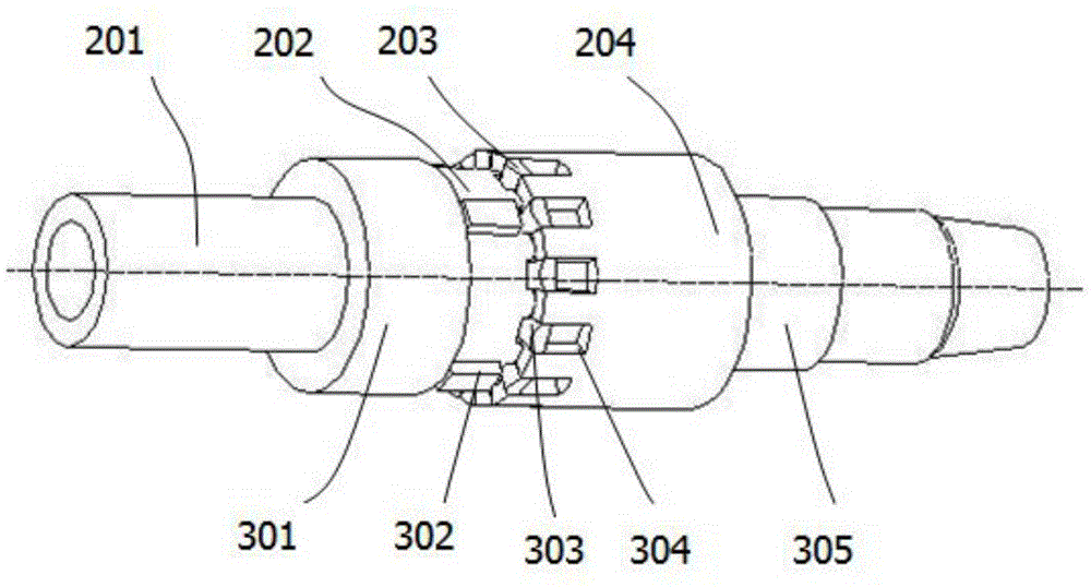
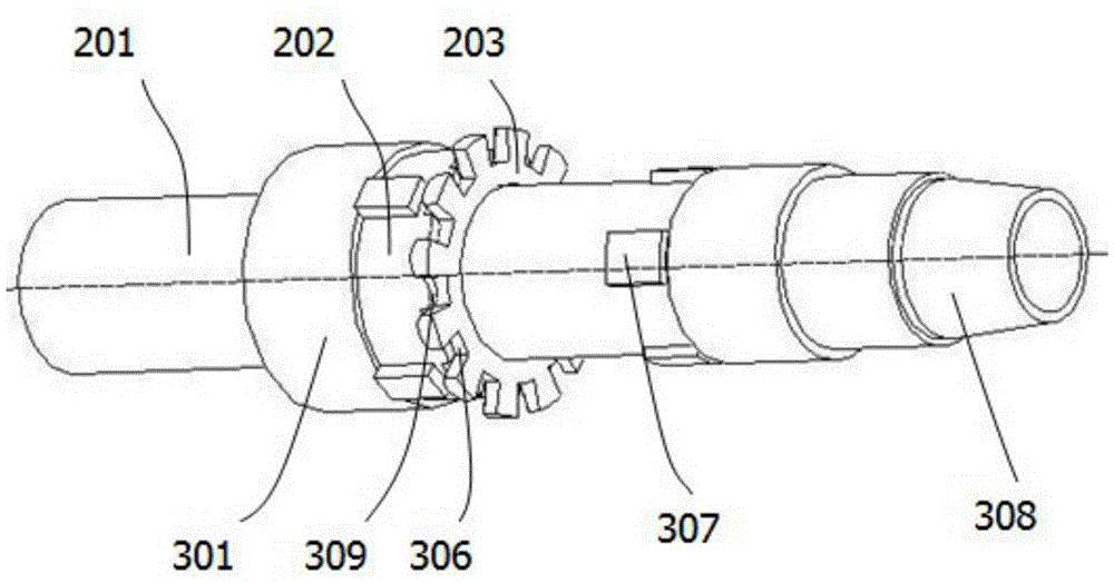
[0040] Such as Figure 1 to Figure 12 As shown, the overload protection device 102 is composed of an upper spline 202 , a driving spline 203 , a lower spline 1 204 and a spring 205 . Among them, the upper spline 202, the transmission spline 203, the lower spline 1 204 and the spring 205 are all coaxial with the central shaft 201, and one end is in contact with the step of the central shaft 201, and the other end is matched with the transmission spline 203, and the transmission spline 203 cooperates with lower spline one 204. The step A301 of the central shaft 201 restricts the upper spline 202 to move leftward along the central shaft 201, and the lock nut 405 matched with the thread A305 restricts the lower spline 1 204 to move rightward along the central shaft 201, and provides spring 205 with initial compressive force.

[0041] The power outer cylinder 101 is equivalent to the load input shaft and is connected with the upper drill string; the bearing assembly 103 is used to ...

Embodiment 2

[0055] Such as figure 1 , Figure 5 , Figure 6 , Figure 7 , Figure 12 As shown, the overload protection device 102 is composed of an upper spline 202 , a lower spline 2 206 and a spring 205 . Among them, the upper spline 202, the second spline 206 and the spring 205 are all coaxial with the central shaft 201, and one end is in contact with the step of the central shaft 201, and the other end is matched with the transmission spline 203, and the transmission spline 203 and the lower spline Two 206 cooperation. The step A301 of the central shaft 201 restricts the upper spline 202 to move leftward along the central shaft 201, and the locking nut 405 matched with the thread A305 restricts the lower spline 2 206 to move rightward along the central shaft 201, and provides spring 205 with initial compressive force.

[0056] The power outer cylinder 101 is equivalent to the load input shaft and is connected with the upper drill string; the bearing assembly 103 is used to bear ...


PUM


Abstract

The invention discloses a torque overload protection tool. The torque overload protection tool is characterized by comprising an outer power cylinder, an overload protection device, a bearing assembly, a sealing assembly and an output shaft. The overload protection device comprises a center shaft, an upper spline, a lower transmission device, a spring and a lock nut; the upper spline, the lower transmission device, the spring and the lock nut are coaxial with the center shaft; torque is transmitted between the upper spline and a first lower spline through a transmission spline; the outer power cylinder is connected with the overload protection device, the lower portion of the overload protection device is sequentially connected with the bearing assembly and the sealing assembly, and the center shaft is connected with the output shaft. Due to sliding contact of contact faces between the upper spline and the lower transmission device, the torque value is controlled by compressing force of the spring; when rotating torque exceeds set overload torque, internal rotation is achieved, and damage caused by excessive torque to a downhole tool connected with the center shaft is avoided; when the rotating torque does not exceed set separation torque, the torque can be output continuously, and working is completed.

Description

technical field [0001] The invention relates to the field of oil and gas field development, in particular to a torque overload protection tool. Background technique [0002] In the process of oil and gas field development, drilling and workover are the main operation steps. It is necessary to use the rotary table and top drive to rotate the drill bit to break the rock from the ground, or use the screw motor to provide the drill bit to rotate and break the rock from the downhole. Either way, the ultimate torque transfer to the drill bit (or other drill tool assembly) is through the drill pipe or drill collar. During the drilling process, different formations exert different resistances on the drill bit. This resistance makes the torque transmitted by the drill string exceed the normal drilling torque, which may cause damage or breakage of the drill string. Most drill strings can only transmit a certain torque, which is too large. The downhole tool cannot be overloaded when t...

Claims


Application Information

Patent Timeline
Patent Type & Authority Applications(China)
IPC IPC(8): E21B4/00
CPCE21B4/006
Inventor 王川周旭王国荣黎俊谢真强
Owner SOUTHWEST PETROLEUM UNIV
Learn More