
Steel-rail detection device

A technology for detection devices and rails, which is applied to tracks, measuring instruments, and track maintenance, and can solve problems such as low efficiency, poor precision, and unsatisfactory requirements

Active Publication Date: 2016-05-11
CHINA SHENHUA ENERGY CO LTD +1
View PDF5 Cites 5 Cited by
  • Summary
  • Abstract
  • Description
  • Claims
  • Application Information

AI Technical Summary

Problems solved by technology

At present, the railway engineering department generally uses observation piles buried on both sides of the track to measure the creepage of the rails, marking the rails, and using artificial strings to measure the creepage of the rails. This method has defects such as poor accuracy and low efficiency.
For time-critical railway skylights, the requirements cannot be met

Method used


Image

  • Steel-rail detection device
  • Steel-rail detection device

Examples


Embodiment Construction

[0019] Specific embodiments of the present invention will be described in detail below in conjunction with the accompanying drawings. It should be understood that the specific embodiments described here are only used to illustrate and explain the present invention, and are not intended to limit the present invention.

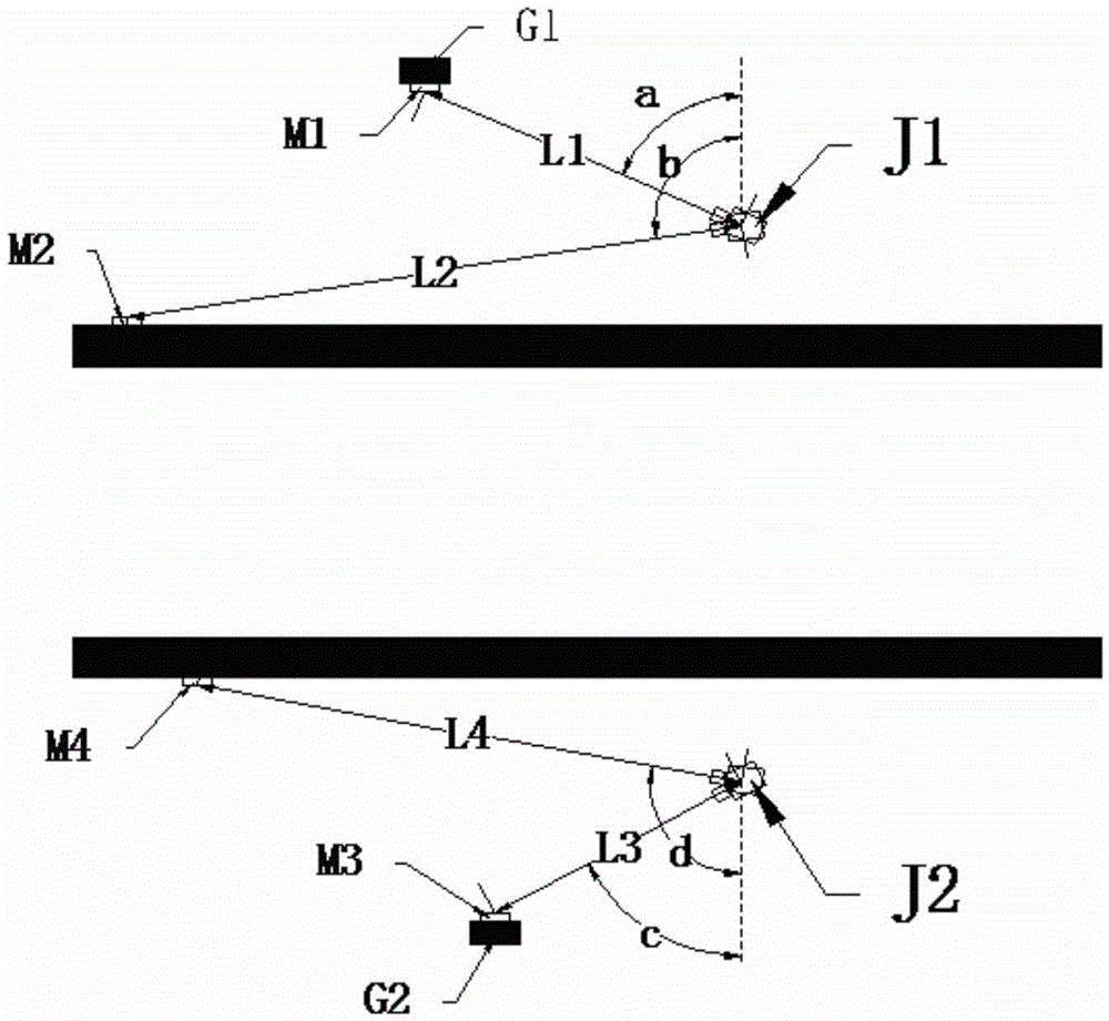
[0020] figure 1 A structural block diagram of the rail detection device provided by the present invention is shown. Such as figure 1 As shown, the present invention provides a rail detection device, which includes: a first observation pile installed at a predetermined distance from one side of the rail; a distance measuring device 100 for measuring the distance between the first observation pile and the rail. the current longitudinal distance on one side; and the control device 200, which is configured to use the difference between the initial longitudinal distance between the first observation pile and one side of the rail and the current longitudinal distanc...


PUM


Abstract

The invention relates to the field of railways, and discloses a steel-rail detection device. The steel-rail detection device comprises a first observation pile, a distance measuring device and a control device, wherein the first observation pile is mounted a preset distance away from one side of a steel rail; the distance measuring device is used for measuring a present longitudinal distance between the first observation pile and one side of the steel rail; the control device is used for confirming the crawling amount according to the difference between an initial longitudinal distance between the first observation pile and one side of the steel rail and a present longitudinal distance between the first observation pile and one side of the steel rail.

Description

technical field [0001] The invention relates to the field of railways, in particular to a rail detection device. Background technique [0002] When the train is running on the track, due to the rolling, traction, braking of the wheels and the temperature stress of the current seamless line, the rail will be displaced in the longitudinal direction, that is, the rail will crawl. Excessive crawling of the rails will cause the rails to fail to generate large tensile and compressive stresses. In severe cases, rail breakage or rail expansion accidents may occur, affecting driving safety. [0003] The railway engineering department must regularly inspect the crawling amount of the rails. At present, the railway engineering department generally uses observation piles buried on both sides of the track to measure the creepage of the rails, marking the rails, and using artificial strings to measure the creepage of the rails. This method has defects such as poor accuracy and low effici...

Claims


Application Information

Patent Timeline
IPC IPC(8): E01B35/12
CPCE01B35/12
Inventor 常晓东许玉德孙小辉李海锋周宇
Owner CHINA SHENHUA ENERGY CO LTD
Learn More