


Quick Research
Generate reliable direction feasibility study reports for your R&D in just a few steps.

Technical Q&A
Discover and master advanced knowledge NOW. Basics, ideas, possibilities, all at once.

Find Solutions
As an expert in R&D theories, this can generate solutions to your technical problems instantly.

Evaluate Feasibility
Analyze your overall solution with one click, know your potential R&D risks in advance.

Monitor Landscape
Get weekly tech updates, stay abreast of the latest tech innovations and key insights.
Three-dimensional inner finned pipe machining cutter
An inner rib tube, three-dimensional technology, applied in the field of three-dimensional inner rib tube processing tool design, can solve the problems of different service life of the cutter teeth, affecting the service life, affecting the heat exchange efficiency, etc., to achieve a simple structure, prolong the overall service life, The effect of ensuring production efficiency and production quality
- Summary
- Abstract
- Description
- Claims
- Application Information
AI Technical Summary
Problems solved by technology
Method used
Image

Examples
Embodiment 1
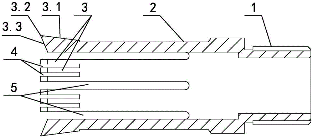
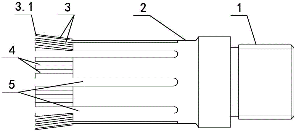
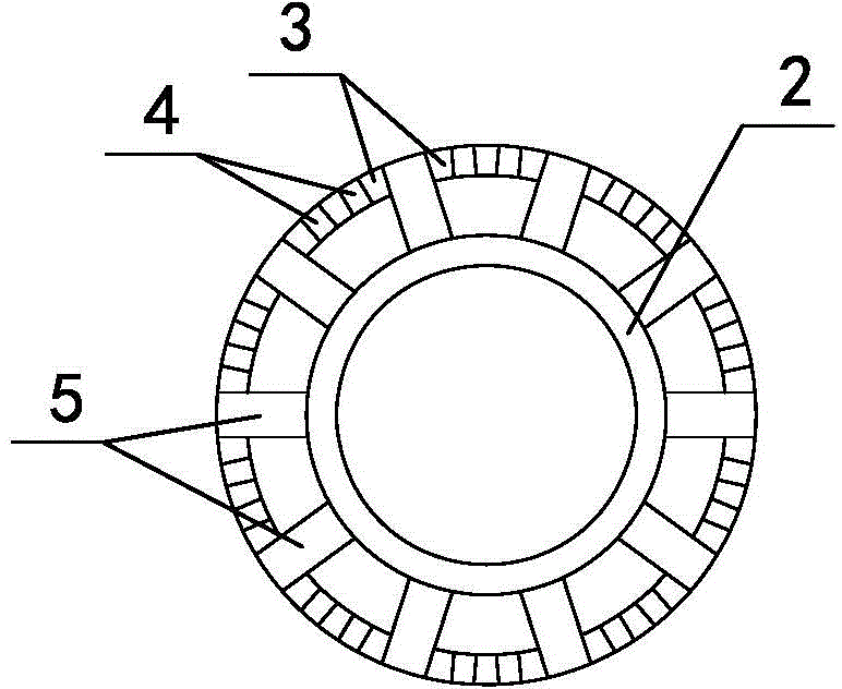
[0021] like figure 1 , figure 2 , image 3 As shown, including the cutter head 2, the cutter head 2 is cylindrical, and several cutter teeth 3 are arranged on the circumference of the left end of the cutter head 2. Between each cutter tooth 3, there are grooves 4 between the cutter teeth, and the cutter teeth 3 The left end is made up of outer cutter face 3.1 and inner cutter face 3.3, and the left ends of outer cutter face 3.1 and inner cutter face 3.3 merge together to become blade 3.2 for processing workpieces, and the cutting edge of blade 3.2 is positioned at cutter tooth 3 outer sides, and inner cutter face The horizontal included angle of 3.3 is 45 degrees, the horizontal included angle of the outer cutter surface 3.1 is 20 degrees, the horizontal height of the blade 3.2 is 2mm higher than the horizontal height of the upper surface of the cutter head 2, and a knife is arranged between two adjacent cutter tooth groups. Tooth contraction joint 5, the knife tooth group ...
Embodiment 2
[0026] Changes are made on the basis of Embodiment 1, the horizontal included angle of the inner cutter face 3.3 is changed to 70 degrees, the horizontal included angle of the outer cutter face 3.1 is changed to 30 degrees, and the horizontal height of the blade 3.2 is higher than that of the upper surface of the cutter head 2 The height of the horizontal height becomes 3mm, and other is the same as embodiment one.
Embodiment 3
[0028] Changes are made on the basis of Embodiment 1, the horizontal included angle of the inner cutter face 3.3 is changed to 60 degrees, the horizontal included angle of the outer cutter face 3.1 is changed to 25 degrees, and the horizontal height of the blade 3.2 is higher than that of the upper surface of the cutter head 2 The height of the horizontal height becomes 2.5mm, and other is the same as embodiment one.
PUM
 Abstract
Description
Claims
Application Information
 - R&D Engineer
- R&D Manager
- IP Professional
- Industry Leading Data Capabilities
- Powerful AI technology
- Patent DNA Extraction
Browse by: Latest US Patents, China's latest patents, Technical Efficacy Thesaurus, Application Domain, Technology Topic, Popular Technical Reports.
© 2024 PatSnap. All rights reserved.Legal|Privacy policy|Modern Slavery Act Transparency Statement|Sitemap|About US| Contact US: help@patsnap.com